


Project type: Bridge Renovation and Public Art Installation
Location: New Britain, CT
Stage: Project is in final inspections
Client: City of New Britain
Project team:
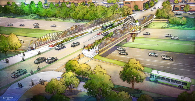
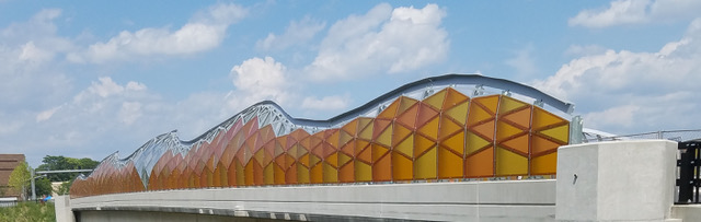
The “Beehive Bridge” is a 265-foot-long highway overpass in the city of New Britain, Connecticut, connecting the two parts of the city that are divided by a highway. Svigals + Partner created a design scheme for a pedestrian-friendly streetscape with an abstract take on the “beehive” theme that has long been associated with New Britain—it features colorful translucent panels in an abstract honeycomb pattern that separate the overpass visually from the highway below (Figure 1). In shades of gold and yellow, the panels produce a variety of patterns and colors depending on the time of day and position of the sun. Building on the theme, the design then incorporates contemporary artwork integrated directly into the structure: four large-format stainless-steel honeybee sculptures, and an outsized beehive in the center of the bridge. Energy-efficient LED lighting illuminates the bridge, ensuring safety for pedestrians and cyclists after dark.
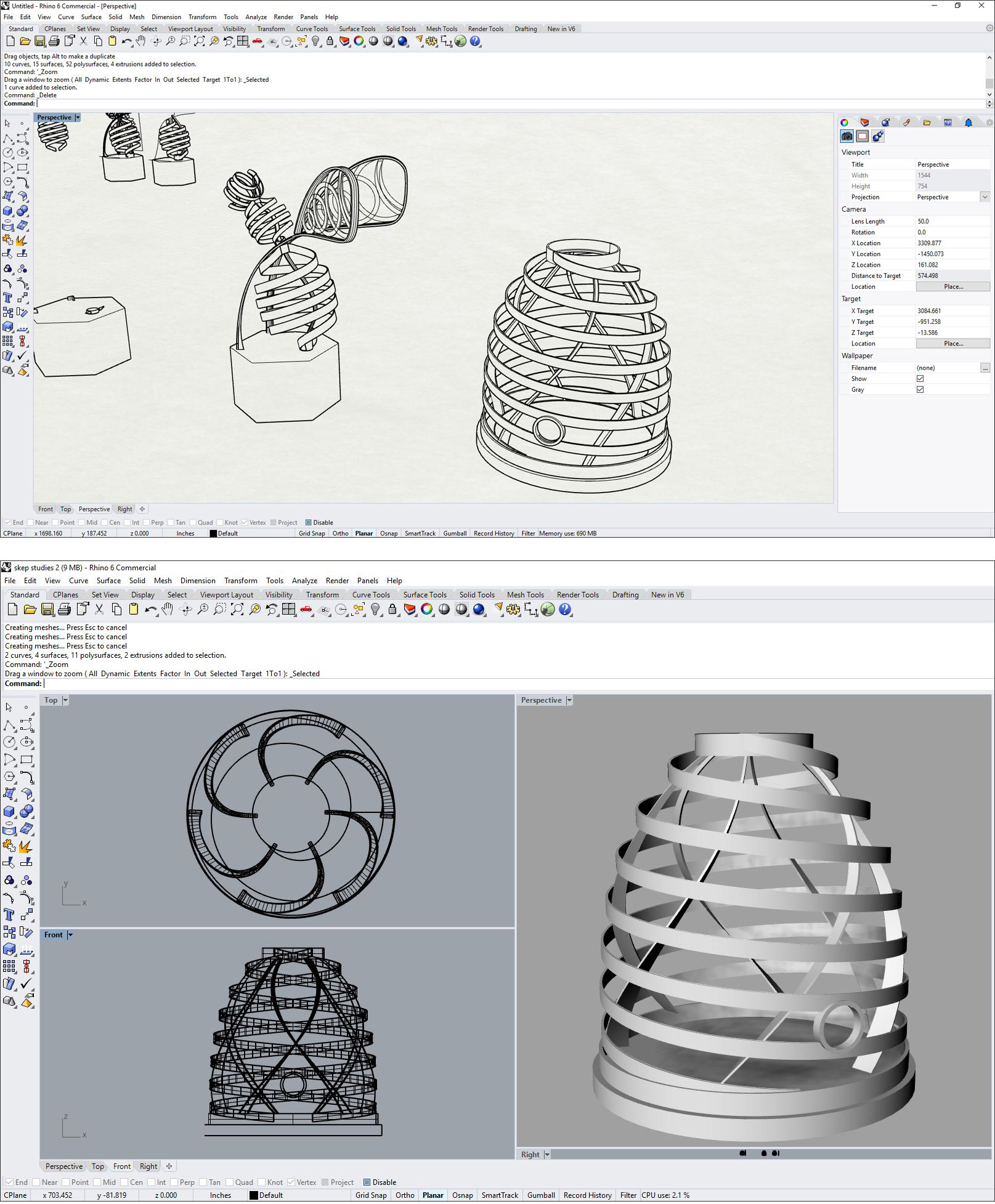
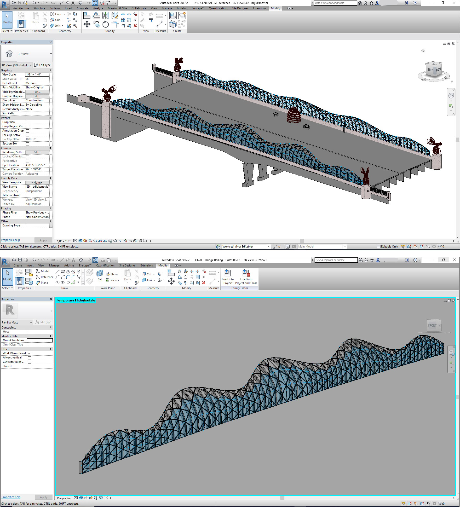
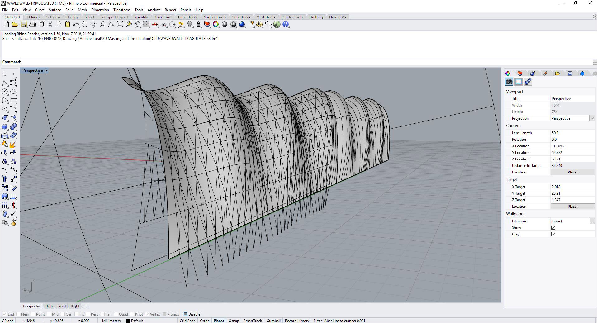
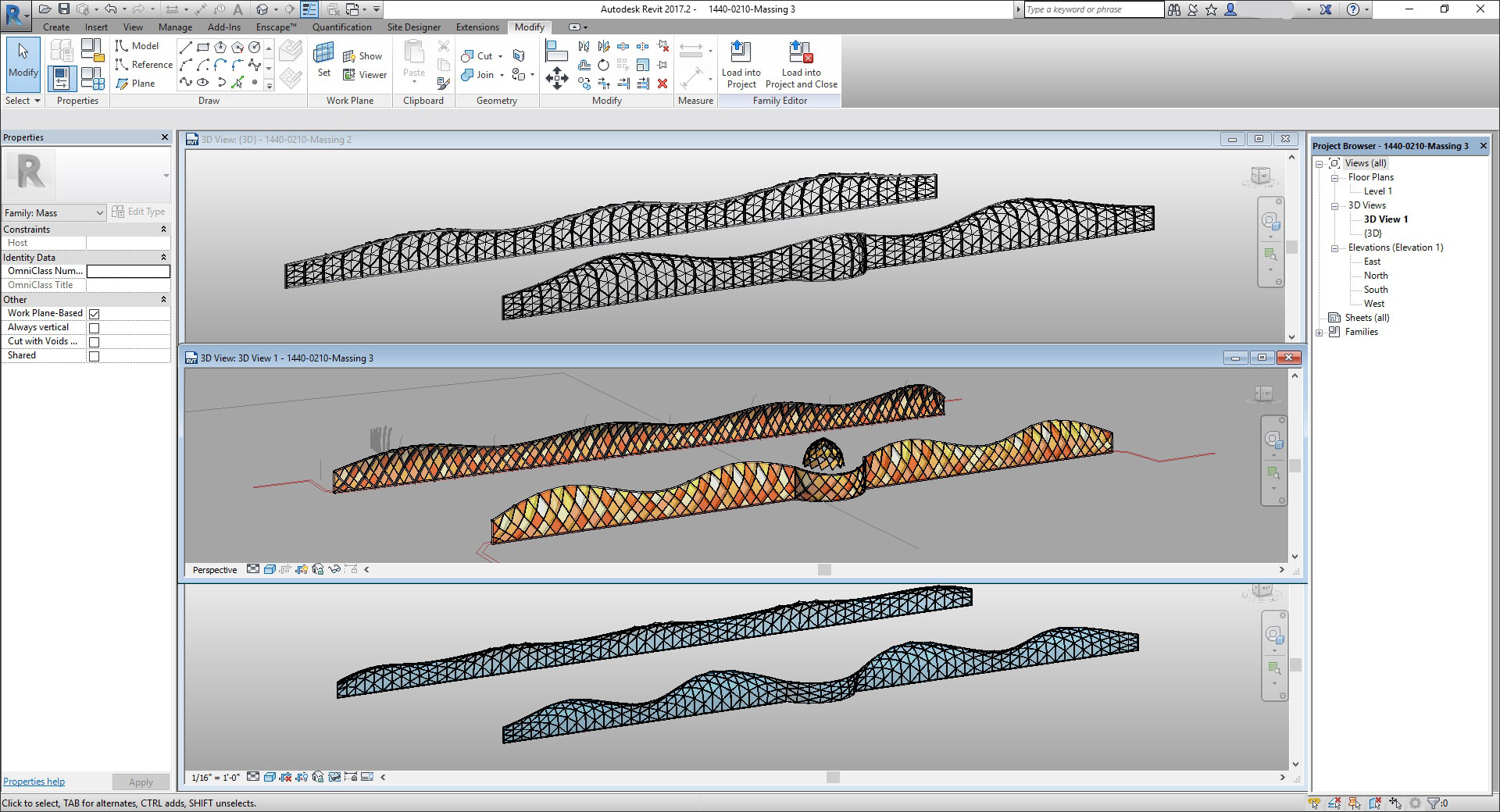
The two main software applications used were Rhino and Revit. Rhino was used for early massing studies of the bridge railing and the development of the sculptural elements (Figure 2). We then moved to Revit for the development of the bridge railing and project documentation (Figure 3).
To optimize the process of documenting the railing design, it was important for the team to keep all production work in a single program. Keeping all our design exploration and creation of the construction document set in Revit allowed for efficient modifications of design that could be immediately translated to the drawings.
As a firm specializing in architecturally-integrated art, a combination of physical and digital modeling is essential to our design process. The use of Rhino allowed us to quickly develop, test, and template sculptural forms in 3D before building physical models in paper, metal, and resin.
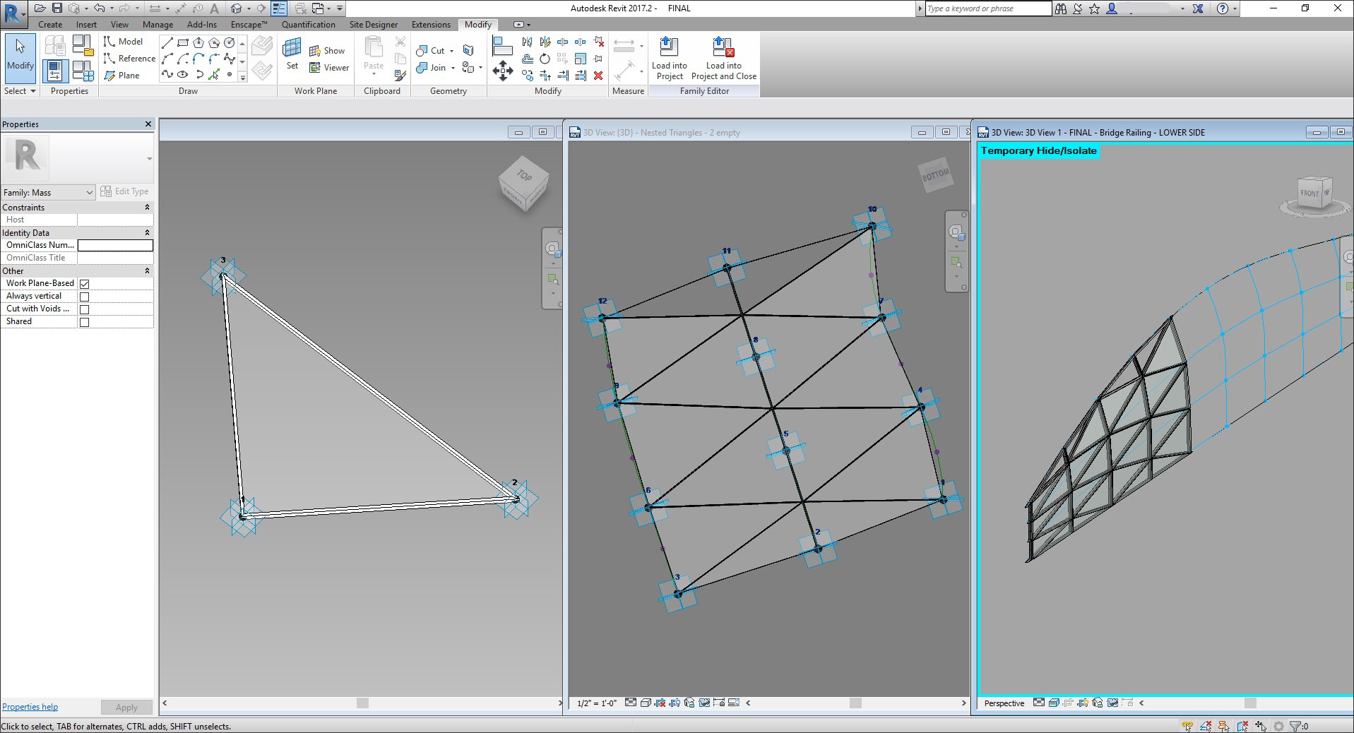
The irregular shape of the rail was defined by its curving grid and triangular panels with edges supported by steel posts (Figure 4). Using advanced Revit modeling techniques, we created smart forms and components with the use of parameters and adaptive modeling. Adaptive components were employed to smoothly manipulate the triangular families into different positions on the railing grid, following parametric rules and adapting to multiple insertion points, and creating a synchronized geometry of triangular panels repeating on an organic curve (Figure 5).
This technique allowed for easier manipulation of the curve radius and creation of multiple panel modules that flexibly adapt to various curve conditions. As a result, the team explored multiple design alternatives with very quick turnaround times.
While parametric modeling in Revit has been around for a while, this was our office’s first venture into this type of computational design. It offered us powerful tools to streamline the workflow. Since this bridge is experienced at close range by pedestrians and from afar by vehicular traffic, the scale of the panels and feel of the curve played a crucial role in how the bridge is perceived and experienced.
In search of the ideal form, multiple analyses of the railing curvature were performed, including review of various individual panel sizes, post spacing, and curve radii (Figure 6). This was also the first time we used Rhino models to create final details in our construction documents.
From the preliminary design stage, the team was aware that the unique shape of the railing would require close coordination with the contractors. With the number of individual elements to be documented, the use of the Alias plug-in provided the ability to flatten the curve and extract individual panel dimensions, while Revit provided the documentation of the geometry. Since no two panels are alike, this was an exciting step toward providing a simplified layout for the fabricator to utilize in production.
The fabricator ended up using our Revit model itself, which helped convey the complexity and feasibility of the design. The collaborative approach between teams resulted in a smooth construction process and a perfectly executed design.
Each panel of the railing is unique, so there are very few identical components in this design. One thing we would do differently in the future is to create an automated scheduling or categorization of individual parts.
Because the parametric model and Rhino models were developed with a high level of precision, our files were a valuable resource for fabrication teams. The availability of digital files cut down on development time for the fabrication engineers, ultimately lowering the cost of the project.
Acknowledgments: The responses to the questions for this profile were provided by Svigals + Partners. The profile was facilitated by Adam Sullivan of C.C. Sullivan.
Have comments or feedback on this article? Visit its AECbytes blog posting to share them with other readers or see what others have to say.
AECbytes content should not be reproduced on any other website, blog, print publication, or newsletter without permission.