


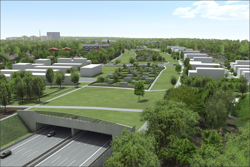
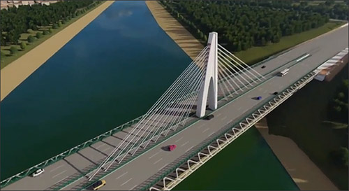
With volumes of over 150,000 vehicles daily, the A7 highway north of the Elbe Tunnel in Hamburg has long established its reputation as one of the most traffic-dense roads in Germany. Recognizing the need for expansion, plans were initiated in 2007 to broaden the highway section from ten to twelve lanes. However, the impact of traffic congestion not only affects the road users, but also — and more importantly — the local inhabitants. Consequently, the highway expansion project also incorporates significant enhancements in noise protection.
To achieve this, three new noise protection covers will be added to the A7 in Hamburg by 2028, located in Schnelsen, Stellingen, and Altona. This will transform the regions previously bisected by the open highways into lush green spaces composed of allotments, floral meadows, and city parks, forging a verdant connection between the divided districts. The Altona noise protection cover is the metaphorical jewel in the crown, spanning approximately 2,230 meters and marking the final stage of this monumental infrastructure project. A collaboration of HOCHTIEF Infrastructure GmbH and Implenia is at the helm of its design and construction, while a planning consortium of HOCHTIEF Engineering GmbH and KREBS+KIEFER Ingenieure GmbH primarily leads the approval and execution planning (phases 4 and 5).
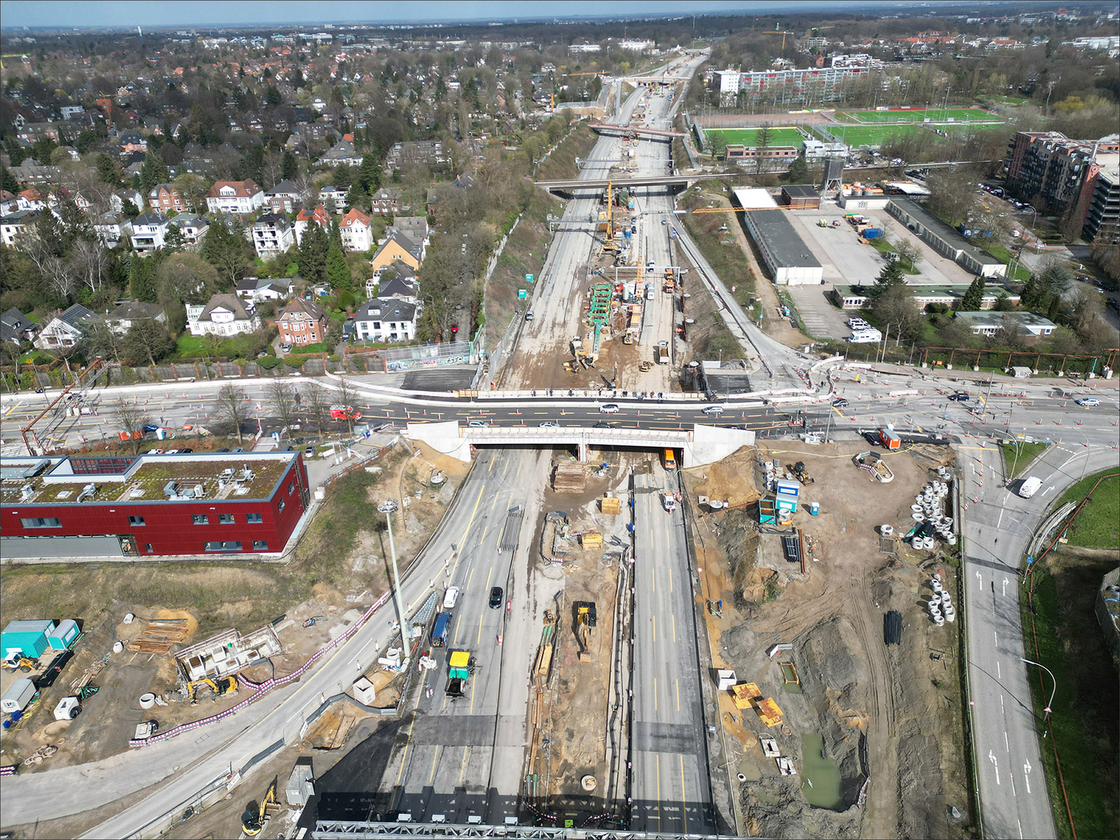
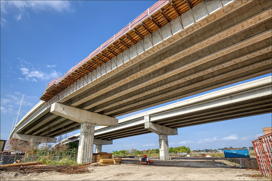
The Altona Cover project is a comprehensive endeavor that encompasses more than merely the installation of a noise protection cover. Integral to the project is the erection of approximately 4,500 meters of retaining wall, and the demolition of three existing bridges to be replaced with new overpasses integrated into the tunnel cells. The technical requirements for traffic and operations involve the construction or modification of traffic sign bridges, two operational buildings, and 14 escape and operational staircases. Additional noise protection will be provided by a 700-meter-long wall in the northern connection area, aiming to further diminish the effects on the local residents.
One distinctive element to consider in the project planning is the elevated groundwater level between the Elbe tunnel and the S-Bahn bridge. Presently, for the ongoing highway operation, this groundwater is reduced via a well system, which discharges unused water into the Elbe. To cut operating costs, the plan envisions a sealed tunnel that includes a combined pile and slab foundation.
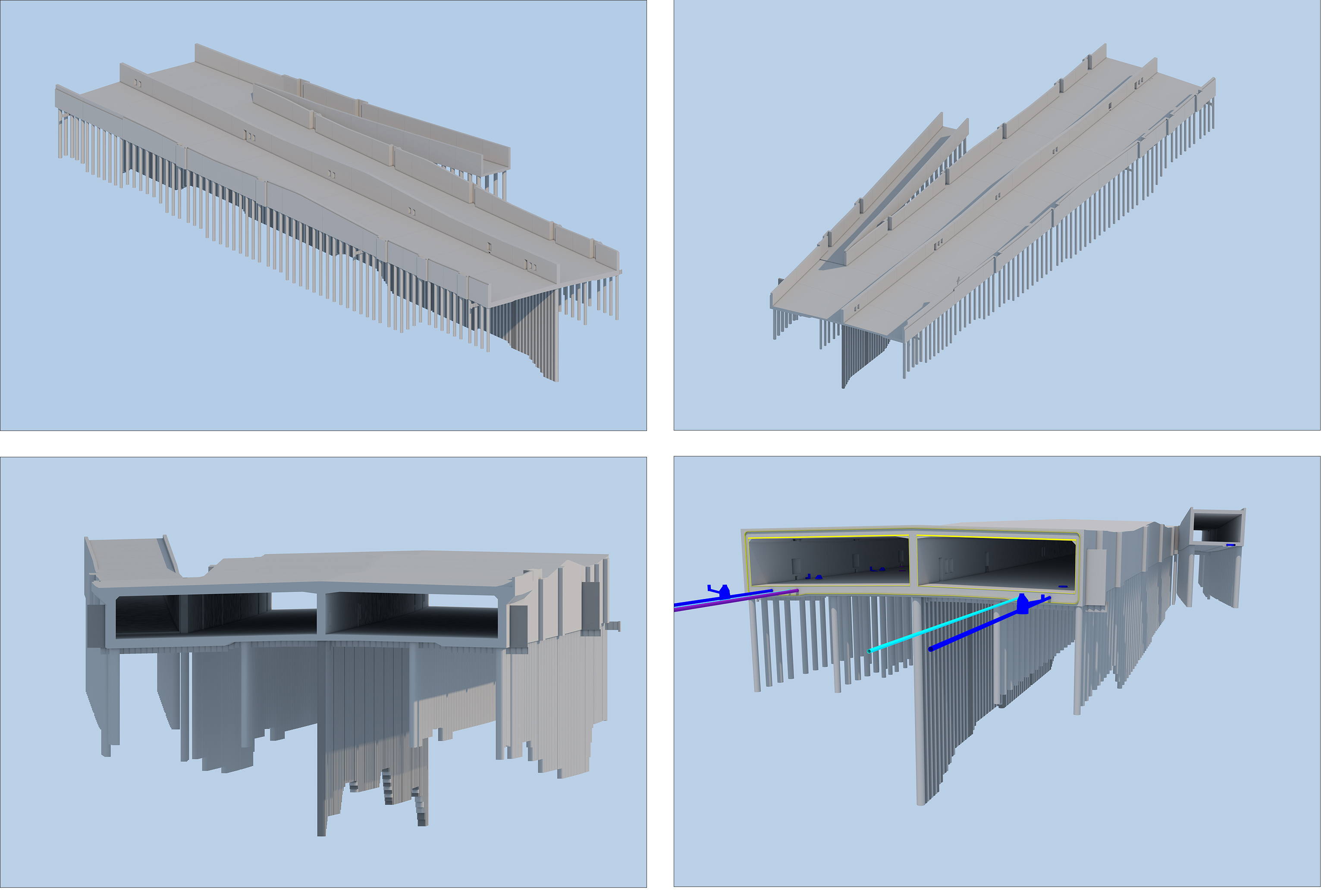
The noise protection cover showcases numerous other variations in its foundational structure; certain regions will be constructed as dual-row large-bore piles topped with pile-head beams. Slabs also differ, mostly comprising of cast-in-place concrete reinforced with bonded steel, though some will be prestressed or assembled using semi-precast elements supplemented by cast-in-place concrete.
HOCHTIEF Engineering has been given the responsibility of carrying out the execution planning for the enclosed segment of the tunnel. The tunnel is designed with two directional lanes — for Hanover and Flensburg — separated by a central tunnel wall. Each of these two tunnel sections accommodates four lanes along with additional turning lanes and hard shoulders.
Designing the structure accurately and in line with the BIM execution plan is a significant planning challenge given its frequently changing cross-sections. At the same time, the gradient and specific details of the corresponding stationing (route kilometers) must also be taken into account. Because of the installations at the slab's lower edges, including light signals, traffic signs, fans, and so on, the tunnel's clear height varies. Similarly, the highway's on- and off-ramps impact the tunnel's width. Concurrently, the tunnel walls need niches or protrusions for technical and safety installations such as electrical equipment, emergency call pillars, fire hydrants, etc., and escape door openings.
Engineers opted to use parametric modeling in Allplan Bridge to create an accurate 3D model encapsulating all necessary details without excessive effort. Using this software, changes to cross-sections — like slab and ramp expansions or niches in the center and outer walls — can be produced along an axis with parametric cross-sections and their associated variation tables.
Brit Krumrey, Senior Design Engineer at HOCHTIEF Engineering, explained, "Allplan Bridge is not only suitable for creating 3D bridges, but also all 3D roadway structures bound to an alignment axis. In our case, we generated the tunnel cross-sections parametrically, enabling us to detail the tunnel's specific features depending on the gradient's path and corresponding stationing."
The stationing is ascertained from the axis and gradient data imported into Allplan Bridge. The parametric cross-sections are calculated in all their variations along these axes and are ultimately joined to form a 3D structure. Given that Allplan Bridge permits multiple axes and gradients to be read and allocated to the relevant cross-sections, the varying gradient curves of the roadways could also be considered during the modeling process.
Once the parametric modeling of the tunnel was conducted in Allplan Bridge, including the creation of the invert, walls, slabs, and all ancillary features like niches, openings, construction joints, and block joints, further enhancements were made to the yet unfinished model using Allplan AEC. During this phase, additional components and fine details were incorporated such as bored piles, cut-off walls made from sheet pile sections (located at the invert's bottom edge), anchor rails (on the walls and slabs), crossing empty conduits (in the invert), and all joint tapes and plates.
This comprehensive model of the tunnel was then used to automatically generate the formwork plans in certain instances (covering aspects such as the bored pile foundation, invert inclusive of drainage pipes, shafts, outer and middle walls, and slabs, incorporating all built-in parts).
The seamless exchange of data with external planning stakeholders — like the ones dealing with the connecting tunnel blocks or drainage pipes — was facilitated via the IFC interface through Open BIM. This ensured that external specialists could utilize their preferred software, with no risk of data loss.
Disclaimer: The views and opinions expressed in AECbytes sponsored articles are those of the sponsor and do not represent or reflect the views of AECbytes.
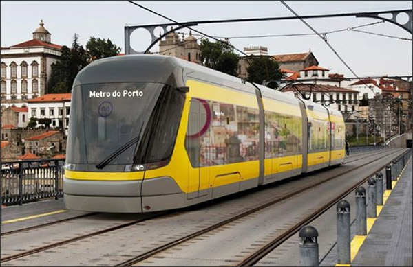
This article shows how being open to change and flexibly adapting to a new way of working, with an approach of “Projects in BIM, not BIM in Projects” using Allplan, helped QUADRANTE, a renowned international consulting engineering firm, successfully deliver a complex new metro line in Porto, Portugal.
This article provides an overview of some of the projects that were presented at ALLPLAN’s recent digital conference by AEC firms all over the world including Ardanuy Ingeniería, Xingtai Transportation Construction Group, Quadrante, and Michael Baker International.
Key updates include full BIM for Precast capabilities, expansion of 3D site planning, improved point cloud support, live links to Solibri and Lumion, expanded steel connection design, automated reinforcement, and several enhancements to Allplan Bridge.
This article describes the recent updates to Allplan Bridge that enable it to easily model precast girder bridges. With just one bridge model, an entire BIM-supported bridge design process can be carried out with this solution.