


With the rise of Building Information Modeling (BIM) being used for infrastructure, 3D bridge modeling has become more popular. However, most modeling techniques are particularly suited to bridges whose geometry is governed by the bridge axis or alignment. As bridges come in many types and each requires different construction methods, some require a different approach to modeling. Precast girder bridges are one example of this, as their geometry is only indirectly governed by the axis.
Precast concrete bridges have been in use since the late 1950s and are commonly used for highway bridges. Because precasting eliminates many on-site, in-situ work processes, construction time and costs are reduced, and quality is improved. The rapid erection enables contractors to work on more projects simultaneously and poor weather conditions have a minimal effect on the construction schedule. In addition, the economy and high quality of prefabricated girders creates savings for transport authorities while minimizing the environmental impact and disruption to the local area during construction.
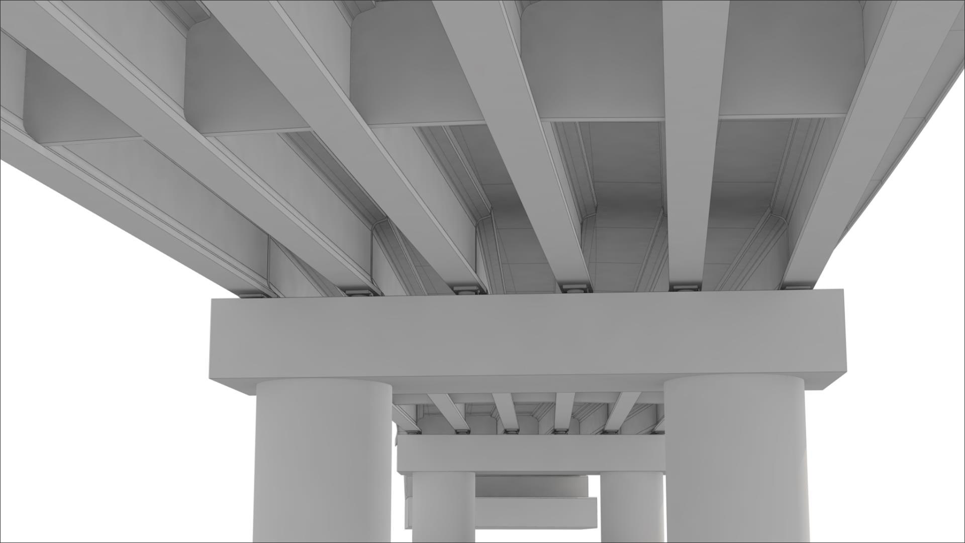
While there are different types of precast girder bridges, they all have one thing in common — their component geometry. The straight profile of precast girders is why their geometry is not directly impacted by the road or bridge axis (Figure 1). Similarly, their final position on the bridge is dictated by the geometry of the supporting substructure. That is why precast girder bridges require a different modeling approach.
Allplan Bridge — a complete, integrated BIM solution for bridges — has been recently updated to address this need. The latest version includes new features that provide an updated modeling workflow, so that precast girder bridges can be created with ease. With just one bridge model, an entire BIM-supported bridge design process can be carried out from within this parametric design solution.
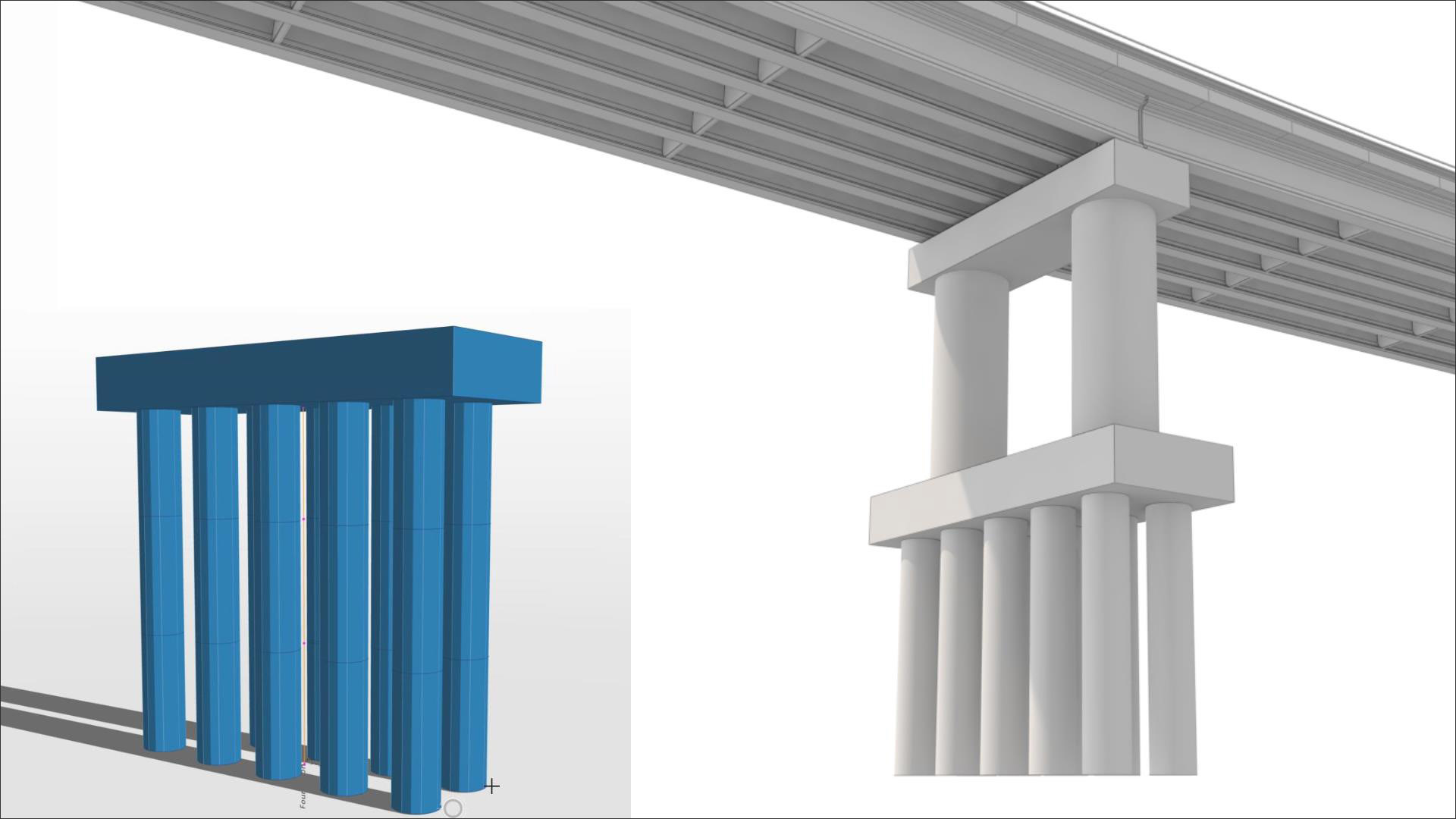
A similar modeling approach to the conventional bridge modeling process is used at first. A bridge axis is created or imported, and the cross-sectional geometry either designed or taken from a template (Figure 2). The substructure is then designed, and next the bridge is ready for the precast girder models to be positioned on top.
To model the precast girders easily and accurately, a new element called Link Girder has been introduced into Allplan Bridge. This is a parametric, linear, 3D element between two 3D points. These two reference points are used for the calculation of the girder geometry, which can be used for a range of applications, including modeling tendons, defining the construction sequence, and even detailing, rebar modeling, and drawing production. Any changes can be implemented quickly and easily by simply adjusting the girder’s parameters.
The reuse of girder shapes and lengths is a typical feature of precast girder bridges. Allplan Bridge includes a new feature called modular modeling that addresses this whilst providing an efficient workflow. Templates for link girder or pier elements can be created with this tool, and simply dragged and dropped into the 3D model as many times as necessary. This way, all the girders can be generated rapidly, saving considerable time.
The girder length can be another time-draining aspect. Either the girder section can vary along the length, the exact length of the girder may vary, or the substructure may be skewed, making it difficult to model the geometry precisely. Overcoming this is easy with Allplan Bridge. Either the template length can be specified as the girder length, or a virtual length can be specified until the girder is positioned on the substructure. Which solution to use depends on the bridge geometry and which is more convenient.
Varying girder sections are also not a problem. Allplan Bridge has new station types — fixed stations — which enable the position where the girder section changes to be fixed. The final girder length can also still be adjusted with the fixed stations remaining in place. Modeling these types of girders is significantly quicker with these tools.
Next, a bridge deck is created by extruding a cross-section along the bridge axis. However, the two bridge elements that have been created up to this point — the girders and plate — will have a gap between them. Creating a haunch to bridge this gap is not straightforward as the 3D geometry for this is influenced by many constraints. For example, the geometry of the deck slab, girder arrangement, construction process and vertical deflections of the girders all influence the haunch geometry. Furthermore, the variable thickness of the haunch may vary along the bridge axis as a result of all the previously mentioned constraints.
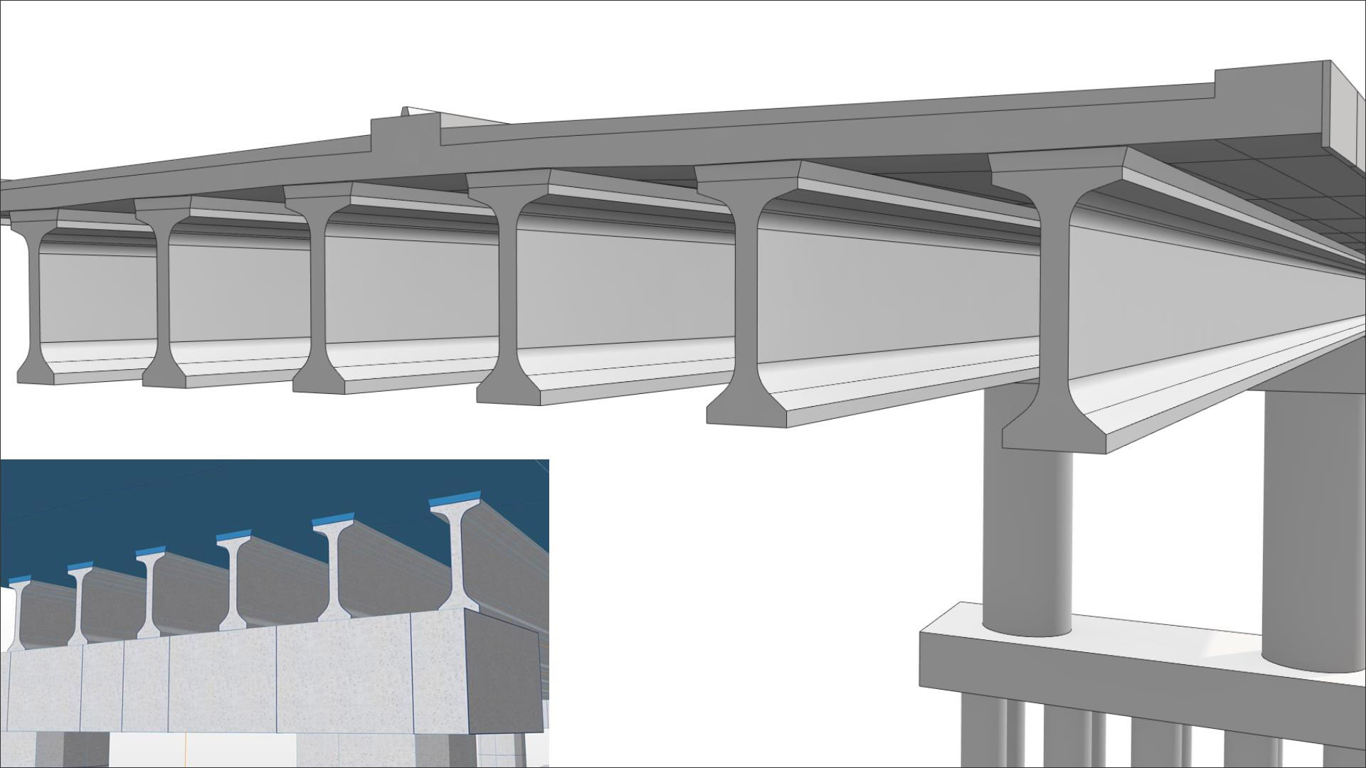
With Allplan Bridge, the haunch can be created quickly and easily by using 3D Boolean operations, as all the parameters which govern the geometry are already defined. (Figure 3) Therefore, the haunch just needs to be pre-defined in such a way that it intersects the deck plate and can be merged with it. To do this, a cross-section of the haunch is created, and then Allplan Bridge automatically calculates and generates the 3D form based on the other bridge parameters.
With the main bridge elements modeled, other details — such as diaphragms, bearings, pavements, barriers, and others — can be easily created. They can be either modeled from scratch, inserted from a library, or created using customized intelligent objects.
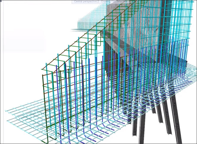
Templates are useful not just for creating girders, but also for modeling the girder reinforcement. This can be easily created using a PythonPart, which enables it to be used multiple times in the same project or across projects, saving considerable time. The template is parametric — just like the girder model —making the placement of reinforcement easier. As the reinforcement’s parameters are linked with the girder model’s parameters, any change to the girder model also automatically changes the reinforcement for easy and efficient adjustments.
Similarly, parametric reinforcement objects overcome the issues traditionally associated with rebar modeling, such as defining rebar shapes, placing the bars, and introducing changes after placement. For example, changing the rebar is as easy as modifying a few parameters and watching the model update automatically.
Together, these new features provide an improved modeling approach specifically tailored for prefabricated girder bridges. The design process is accelerated while enabling a precise model to be generated with ease. As one of the most common bridge types used globally, this can add up to significant time and cost savings.
Additionally, the BIM process is completely supported with the integration and synchronization offered by ALLPLAN’s cloud-based BIM platform, Bimplus. With this new modeling approach for precast girder bridges together with enhanced tools for optimized BIM workflows, Allplan Bridge lets engineers focus on what they do best: designing and building safe and attractive bridges.
Finally, ALLPLAN supports a complete design-to-build approach through their Precast solutions. These include precast detailing, manufacturing work preparation, and manufacture.
To learn more about modeling precast girder bridges, watch the video: Precast Girder Bridge Workflow (allplan.com)
 Gregor Štrekelj is an experienced Structural Bridge Engineer and is the Product Manager for Infrastructure at Allplan Software Engineering GmbH, located in Graz. With a Masters degree from the Technical University in Maribor, Slovenia, specializing in Bridge Engineering, he started his professional career as a Support Engineer and Consultant Bridge Engineer, during which time he was involved in several international bridge projects. Continuing his professional development, he then gained experience as a Product Manager. Driven by a constant desire to provide a best-in-class bridge modeling, analysis, design and detailing solution, Gregor devotes himself in recent years to the Allplan Bridge product and the team behind it.
Disclaimer: The views and opinions expressed in AECbytes sponsored articles are those of the sponsor and do not represent or reflect the views of AECbytes.
This article captures the developments in the software available for BIM for infrastructure, including solutions from Site3D, CGS Labs and SierraSoft, Allplan Civil Engineering and Allplan Bridge, Autodesk Civil 3D and InfraWorks, and the many solutions from Bentley.
This review explores the new features and improvements in Allplan 2022 for navigation, model inspection, visualization, scripting, automated reinforcement, terrain modeling, road design, bridge design, construction scheduling, and more.
AEC projects are continuing to grow in complexity, requiring more time and resources. At the same time, firms are being constantly told that there is a need to do more with less. Frank Holz, Senior Technical Consultant at ALLPLAN Inc, looks at how can this be accomplished with existing staffing levels.
The benefits that 3D modeling and BIM offer reach much further than just faster detailing drawings. Modeling reinforcement in 3D can make the entire rebar detailing process much more streamlined and efficient, saving valuable time, money, and effort.