


Revit’s coordinate system has been a hot topic since it started, and it seems like it’s a challenge even for the most experienced users. There is a lot of information about Shared Coordinates, yet it is still the number one cause of frustration, since even when you do it “by the book,” sometimes things fall out of place. The reason often lies in the wrong preparation of your file at the very beginning of the project, including cleaning your CAD links. However, there is another very common reason why things go wrong: we fail to geolocate our files, to begin with.
In the following article, we’ll make this complicated thing simple and walk you through the steps to geolocate your Revit file correctly with Revit native tools, and also by using the Set Coordinates tool in the Revit plug-in, Environment for Revit, so that everything falls into place.
But first, let’s start by explaining how coordination in Revit actually works.
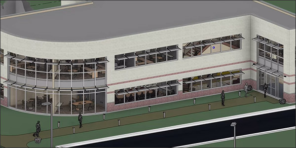
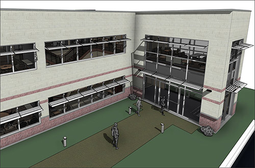
Note: Although written with a special emphasis on site models, this article is also relevant to all Revit users, especially BIM coordinators.
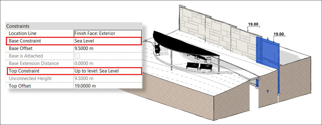
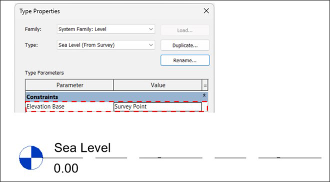
Outside of a building, the height of each element is defined as Absolute elevation, which is above or below sea level. The best practical way of doing it is by adding an Architectural Level that’s called Sea Level and placing it at the 0 elevation.
There are many benefits of working with such a Sea Level in your file, and it’s essential to your site or URS (Unique Reference System) models. Adding a Sea Level helps when you link CAD files into Revit, especially survey data, since the linked CAD has to be placed at a certain Revit level in any case.
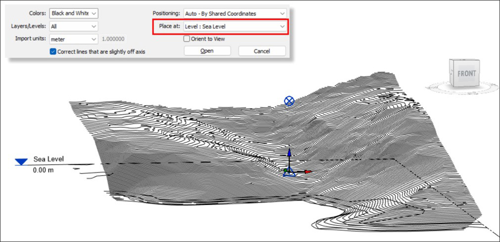
Also, this level is used as a constraint for site elements such as Walls and Floors, which are not a part of a building, and are always designed and tagged using absolute elevations.
But most importantly, with a dedicated Level, it is much simpler to communicate information since you can name a level Sea Level, and everyone knows what it means. It will also make it easier in the long run to monitor and solve coordination issues and see if someone accidentally moved something.
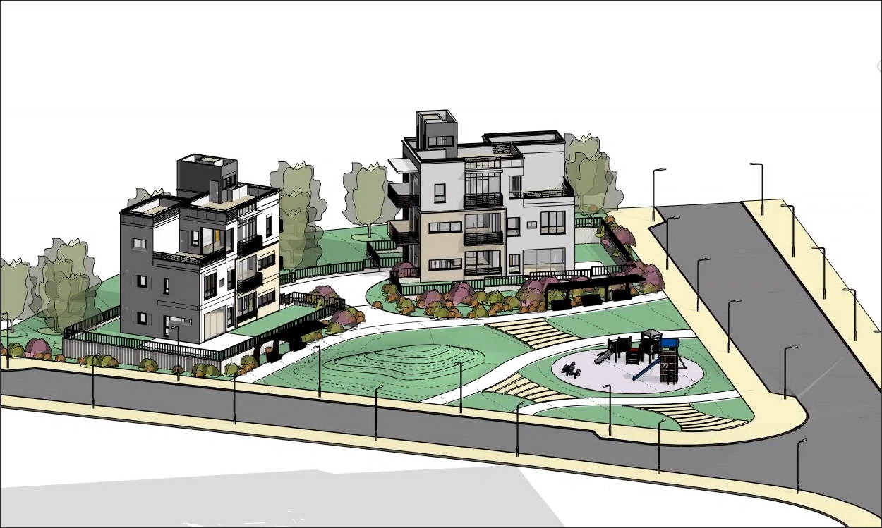
As mentioned earlier, this article is written with landscape architecture in mind. As we see more and more landscape and site designers making the transition to BIM, it is important to lay the groundwork for them to collaborate with the other disciplines in the project. Adding an appropriate level is an important step in this direction.
There is more than one way of measuring and communicating our position on the globe. In Revit, we use two main methods to define our project’s location: the global and the local. Some of you might already know them but still, let’s get our terminology straight.
This is the most common and known coordinate system, and it is composed of a geodetic grid wrapped around a globe. We call these horizontal and vertical lines Latitude and Longitude. (Read more about it here: https://en.wikipedia.org/wiki/Geographic_coordinate_system ). In Revit, we use the GCS to geolocate our project i.e., define its position on Earth.
Although the GCS may be enough to set the address of your project, it's not useful for measuring areas and linear distances between elements in your project.
That is why, to get better accuracy, every country or region has its own named local datum. The datum is a projected (flat) coordinate system or grid, with an origin defined by a GCS point (Latitude and Longitude). The locations in the datum are defined by the X and Y values on the grid. Just imagine taking a chess board and using a pin to locate it on a globe. (Here is where you can search for local datums and compare them to the Lat and Long values: https://epsg.io/)
In Revit, we use the Survey Point to represent the origin of this local Datum.
 Revit has three coordination reference points and all elements in your model relate to these points in one way or another.
Let’s explore the function of each point.
 This is the center of the virtual Revit universe and the only reference for Revit, as software, to understand where things are placed, so all mathematical calculations are done according to this point. Due to mathematical limitations, your model should always be around the IO; preferably, it should be centered around it (You've probably heard about the 20-mile project size in Revit. Just take a 10-mile limit in every direction from the IO and now you get it.) Since the IO is the center of the "universe," it cannot be moved, so when designing the outdoors, it is recommended to keep your Sea Level and IO aligned with each other.
 As already mentioned, this point is here to add the local Datum layer to our location on Earth. Once we acquire coordinates, the Survey point moves to the origin point of the local coordinate system (datum) and its X,Y values will show 0.00. If you want to move your survey point closer to your project, don’t forget to unclip it first, so it will move relative to the 0.00 coordinate in the local datum; otherwise, you will mess up the shared coordinates.
 To be brief, the Project Base Point has no meaning when it comes to geolocation and coordinates, and you can move it freely without it affecting the location of the project. This wasn’t the case in earlier versions of Revit, only since version 2020.
The PBP is mainly used as a project-specific reference point and the team can decide where they want to position it. Usually, the PBP is placed at one of the building’s corners and vertically located at the entrance level of the building. (In architecture, all building elements will most likely be modeled in reference to this elevation, i.e., the height of a level will be measured from the PBP and not from sea level.)
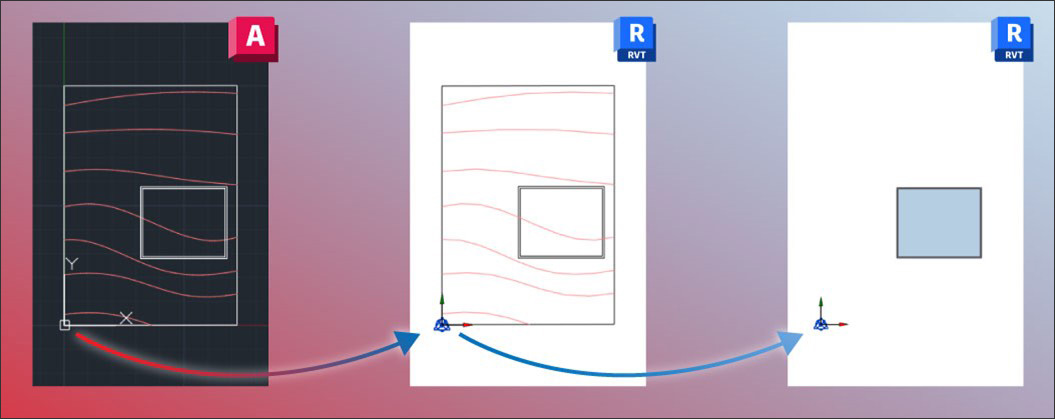
In Revit, we use the Shared Coordinates option to establish a common understanding of positions and distances between elements in the model and to ensure that all project participants share it. As we learned before, we can do it by speaking the common language – Geolocation and local Datum.
When we define a Shared Coordinates system (using the Acquire Coordinates or the Specify Coordinates in Point features), we associate our Internal Origin with a certain position on a local grid (Datum).
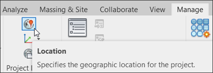
When we set the project location, we want to locate this Internal Origin on the globe and associate it with a certain address or with Latitude and Longitude numbers.
Some of you may have already noticed that this dualism can lead to some very strange situations. For example, you can have your project in the local Israeli Datum and at the same time located in Boston. This is, in short, where most coordination issues begin.
To solve this, we need to make sure that the local datum matches the world geolocation. But in Revit, these two coordination systems are not connected by default. The only way to geolocate your file and make sure you use a conventional named datum is if you acquire coordinates from a geolocated DWG file. However, there is no way in Revit to access this list of local datums and associate your file with one of them manually. So, if you use a simple AutoCAD file for acquiring the coordinates, you're at great risk of struggling with your coordinates later on in the project.
Up until now, we were learning how Revit coordinate system works with the out-of-the-box tools and why we need a geolocated DWG survey file to establish Shared Coordinates in Revit. We will now look at the Set Coordinates tool by Environment for Revit®, which is an external plug-in. This section is mostly a practical guide meant to help you improve your Revit workflow.
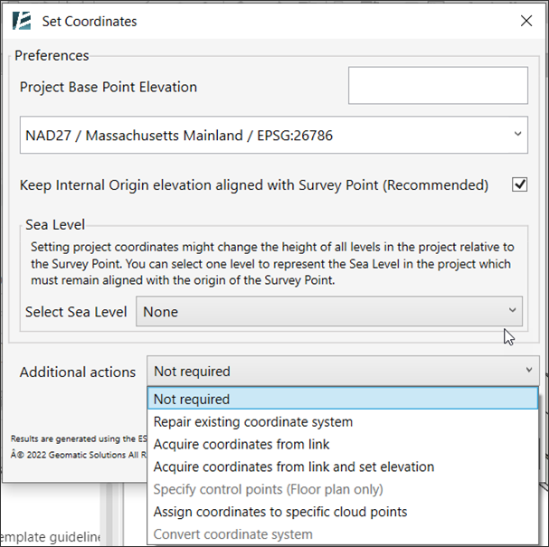
Connecting the world geolocation with the conventional local Datum is exactly what this feature is here to do. It allows you to define the coordinate system and location of your project, but when it comes to location, it can do much more than that.

So, what can the Set Coordinates tool do? Here are six things you can easily achieve with this tool and save loads of time and agony while doing it.
In some cases, you start a new project with no available survey data, but you still want to place it in the correct location to collaborate with others. With this option, you can set up your file by simply entering the project address and the name of the local Datum. Do this, and voila: your project is correctly set up in shared coordinates for the rest of its life.
If your project already has shared coordinates but is not correctly geolocated, you might experience some problems linking files that don’t fall into place (even if they acquired coordinates from the same source). In that case, all you need is to use the Repair option. Just insert the project location (this doesn’t have to be precise) and the name of the used Datum, and you fixed the shared coordinates in the project. This is also useful if you need to fix vertical inaccuracies and essentially move Revit’s Internal Origin back to elevation 0.00 (sea level).
Do you have your survey data but are not sure if it’s geolocated? Do you need to create an accurate URS file for all team members? Use this option whenever you need to acquire coordinates from a linked file, be it CAD or Revit, to make sure your project is also geolocated when doing so. Spoiler: A future version of this tool will allow you to acquire coordinates directly from a linked Point Cloud.
Sometimes you get lucky, and your project manager asks you to switch the coordinate system (datum) while you’re still designing your project. This can be the worst headache possible if it wasn’t for the Set Coordinates that allows you to switch from one system to another in just a few clicks!
The growing community of surveyors using Revit to deliver their survey information poses a need to assign coordinates to new files using some traditional methods. With this feature, you can geolocate your file, select the local system, and assign coordinates by selecting a few known points on your survey and specifying their known coordinates. You can do this based on a PDF, JPG, or a CAD file, and you can also do this based on a point cloud linked into your model. By defining more than one point, we can know the angle from true north and also get more accuracy.
Whether you are an architect, a surveyor, or a BIM coordinator; starting a new project, or working on an ongoing one; a profound understanding of Revit’s shared coordinates is crucial for seamless collaboration. And with the Set Coordinates tool by your side, you can be sure that your project will never get lost in space.
Hopefully this article provided more clarity and was helpful for your daily work. For more in-depth information and step-by-step tutorial, visit our YouTube channel and our website.
 Experienced landscape architect, Revit expert, educator, and lecturer of one of AU 2021’s top rated classes, Nehama Shechter is Arch-Intelligence’s COO and industry coordinator, where she is responsible for the industry leading BIM-based landscape and site design platform, Environment for Revit. Nehama gained her Bachelor of Landscape Architecture degree from the Technion - Israel Institute of Technology in 2016, and she came on board the Arch-Intelligence family after discovering first-hand the grueling and nearly impossible task of learning how to use Revit for site design.
 Ilya Volokin is an Israeli landscape architect with a passion for innovation. After honing his skills designing and building gardens in Ukraine, he arrived in Israel in 2014. There, he designed and led diverse landscape architecture projects at a prominent firm. Fueled by the challenges of using Revit for landscape design, Ilya started to investigate ways to streamline the modelling process through Revit API. This led him to found Arch-Intelligence in 2018. The company's flagship creation, Environment for Revit, is a testament to Ilya's commitment to making BIM workflows accessible for landscape architects.
AECbytes content should not be reproduced on any other website, blog, print publication, or newsletter without permission.
Revit expert Dan Stine provides a detailed overview of the new features in Revit 2025, including toposolid enhancements, improvements to work with materials, improved Project Browser search, enhanced operating schedules and updated gbXML support for sustainable design, and more.
This is a plug-in to Revit that extends its capabilities for site and landscape design, with tools for modeling terrain from scratch, visualizing and analyzing topography, creating outdoor walls and railings quickly along sloped surfaces, and other useful tasks.
Revit expert Dan Stine provides a detailed overview of the new features in the just-released Revit 2024, including generate energy model by view, linking collaboration models, new imperial templates and sample model, revamped site tools, a new Textures view style, and many more.

This article questions why we still don’t have a smart building design tool which does not require us to painstakingly model every detail in our buildings, but can automatically create much of it from a conceptual sketch using a rule-based expert system.