


With the increasing interest in building information modeling in the AEC community, the issue of interoperability as a means to integrate the various model-based applications into a smooth and efficient workflow has emerged to the forefront of professional attention (see my first newsletter on the AIA Technology in Architectural Practice conference held in San Francisco in Oct 2003). And to most AEC professionals, the word interoperability seems to have become synonymous with the IFC effort (see the recent Viewpoint article in AECbytes by Paul Seletsky).
What exactly is the IFC (Industry Foundation Classes)? Most professionals simply know of it as a data model developed by the IAI (International Alliance for Interoperability) to facilitate interoperability in the building industry. While technical information about the IFC building model is documented in detail and is readily available for software developers who need to work with it, there is practically no information for the average AEC practitioner who wants to have a better understanding of the IFC model. The intent of this article is to address this shortfall. It is not about interoperability or data integration per se; rather, it is focused on providing a broad overview of the IFC model without delving too deeply into its technicalities.
Let's start by looking at the basics of a building data model, how it differs from a geometric data model, and why such a model is critical to improving the state of the art in the AEC industry.
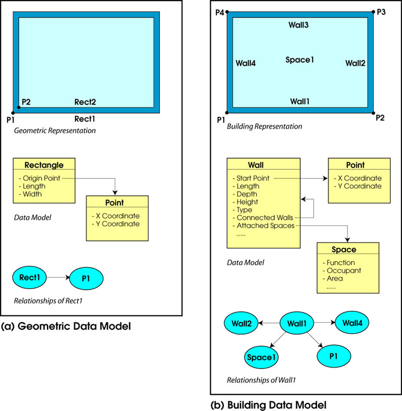
A data model in any given domain describes the attributes of the entities in that domain as well as how these entities are related to each other. Since all computer programs deal with some kind of data, they must have some kind of underlying data model. Traditional 2D CAD and generic 3D modeling programs internally represent data using geometric entities such as points, lines, rectangles, planes, etc. (see Figure 1-a). Thus, while these applications can accurately describe geometry in any domain, they cannot capture domain-specific information about entities. In the case of the AEC industry, technological progress has been severely constrained by the limited intelligence of such applications in representing buildings and being able to extract the relevant information from the representation that is needed for design, analysis, construction management, operation, and so on.
To overcome the limitations of general-purpose geometric representations, every design-related industry has been developing and using object-based data models that are specific to their domain. In the case of the building industry, this translates to a data model that is built around building entities and their relationships to one another (see Figure1-b). Geometry is only one of the properties, among others, of these building entities; thus, its primacy is greatly reduced, even though the interface to creating the model is still mainly graphic. Such a data model is rich in information about the building that can be extracted and used for various purposes, be it documentation, visualization, or analysis.
A simple but critical example of the difference between a geometric data model and a building data model is in the representation of a space. Traditional 2D and 3D CAD programs don't represent a space because it doesn't exist as a distinct physical entity. However, a space entity will be an integral part of a building model, and will include the appropriate relationships to walls, ceilings, floors, and so on (for example, see the simple wall-to-space relationship shown in Figure 1-b). Thus, information about spaces that will be needed, say for energy and egress analysis, can be easily obtained from an application using a building data model, whereas several complex calculations will be required to derive the same information from an application using a geometric data model.
While geometry-model based applications are still widely entrenched in the AEC industry—and largely responsible for its slow progress—the need for a building-specific data model is hardly a new realization. Graphisoft's ArchiCAD application was developed more than 20 years ago based on an object-based building data model; so is the more recent Autodesk Revit. There are also hybrid applications such as Bentley Architecture and Autodesk Architectural Desktop, which have a building data model built on top of the geometric data model of the original CAD application—MicroStation and AutoCAD respectively—on which they are based. All these are applications by commercial vendors and their internal data models are proprietary, which is why they cannot communicate their rich building information directly with each other unless they develop specific translators for this purpose.
The IFC is a similar object-based building data model that is, however, non-proprietary. It has been developed by the IAI, a global consortium of commercial companies and research organizations founded in 1995, whose North American chapter is now part of the National Institute of Building Sciences (NIBS). The IFC model is intended to support interoperability across the individual, discipline-specific applications that are used to design, construct, and operate buildings by capturing information about all aspects of a building throughout its lifecycle. It was specifically developed as a means to exchange model-based data between model-based applications in the AEC and FM industries, and is now supported by most of the major CAD vendors as well as by many downstream analysis applications. With 14 chapters in 19 countries and 650 member companies funding its development, it is a truly global effort.
The IFC effort closely parallels another collaborative representation effort known as STEP (STandard for the Exchange of Product model data). Initiated in 1984 by the International Standards Organization (ISO), STEP was focused on defining standards for the representation and exchange of product information in general, and continues to be used in various design disciplines such as mechanical design, product design, and so on. Several people involved in the STEP effort from the building industry realized that a more domain-specific model was needed for representing building data; they subsequently got involved with the young IAI's IFC effort and brought to it their experience in defining industry-based standards. To this day, the IFC model continues to be closely related to the STEP standard. It uses several resource definitions based on STEP (which will be described in more detail in the next section), and also uses the same modeling language, EXPRESS, for developing and defining the model. In contrast, most contemporary commercial software applications would use some form of UML (Unified Modeling Language) for developing their data models.
The actual development effort of the IFC model is undertaken by the Model Support Group of the IAI, currently comprised of six members located in different parts of the world. The development work has been underway for several years, with regular releases of new versions. The first version of the IFC, version 1.0, was released in 1997. The latest version released in 2003, IFC 2x2, is the seventh. Each subsequent version adds capabilities to represent more entities and more relationships related to a building's lifecycle.
Because the IFC is an open data exchange format that captures building information, it can be used by the commercial building-model based applications to exchange data with each other. This requires the application to be "IFC-compliant," which means that it is capable of importing and exporting IFC files. Applications get the IFC-compliant tag by going through a certification process. The IFC model specification is posted publicly and accessible to anyone, so developers can work with it and build the necessary IFC import and export capabilities into their applications. What this essentially means is that the data has to be mapped between their internal representation and the IFC representation. We'll look further at how this translation works in a subsequent section.
Let's move on to look at the actual model itself in some more detail.
The IFC model
represents not just tangible building components such as walls,
doors, beams, ceilings, furniture, etc., but also more abstract
concepts such as schedules, activities, spaces, organization, construction
costs, etc. in the form of entities All entities can have a number
of properties such as name, geometry, materials, finishes, relationships,
and so on. The latest release of the IFC has a total of 623 entity
definitions, which means that it represents 623 different kinds
of components or concepts.
The main architecture diagram of the IFC model is illustrated in Figure 2, showing how the model has been designed. From the broadest perspective, the model is divided into four separate layers, representing four different levels. Each layer comprises several diverse categories, and it is within each category or schema that the individual entities are defined. For instance, the Wall entity (called IFCWall) falls in the Shared Building Elements schema, which in turn belongs to the Interoperability layer. The layering system is designed in such a way that an entity at a given level can only be related to or reference an entity at the same level or at a lower level, but not an entity at a higher level. The modular design of the overall architecture is intended to make the model easier to maintain and grow, to allow lower-level entities to be reused in higher-level definitions, and to make a clearer distinction between the different AEC/FM disciplinary entities so that the model can be more easily implemented in individual discipline-specific applications.
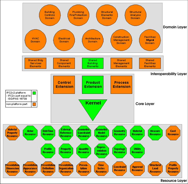
A brief description of the four main layers of the IFC model architecture is given here, starting from the lowest to the highest:
Notice that some of the schemas in the architecture diagram (Figure 2) are colored in green, in contrast to the other schemas that are colored in orange. The green schemas are "part of ISO/PAS 16739"—what this means is that these model definitions have been certified by the ISO (International Standards Organization). In order to qualify for this certification, these model definitions have to meet certain quality control standards. The ISO certification, which was awarded in 2002, is critical to the IFC because it implies a certain level of maturity and stability for that part of the model, which in turn makes it easier for commercial companies to justify implementing it.
Now that we've seen the overall architecture of the IFC model, let's look at a few entity definitions. We will take the example of a wall entity and a space entity, two of the most basic components of any building, and see how they are represented individually as well as how their relationship with each other is represented. This is critical because in working with the building data, we would like to know not only the details of a wall and a space but also about which wall is connected with what space.
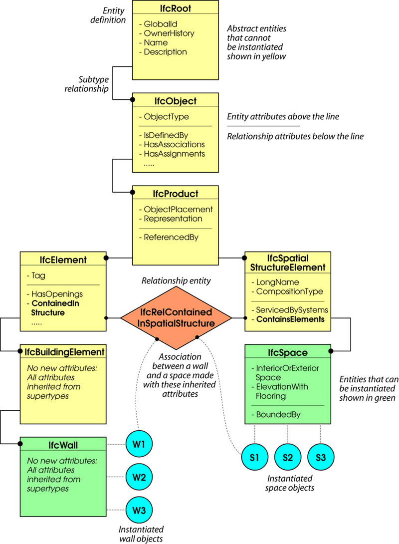
A wall entity, along with other building entities such as a roof, slab, column, beam, etc., is defined by the entity hierarchy shown in Figure 3. What this means is that a Wall entity (IFCWall) is defined as a subtype of the Building Element entity (IFCBuildingElement), which in turn is a subtype of the Element entity (IFCElement), and so on, going all the way up to the Root entity (IFCRoot). Attributes are associated with each type of entity, as shown in Figure 3, and the Wall entity inherits the attributes of all its parent entities (known as supertypes). All the upper-level entities in this case are abstract, which means that you cannot create an actual instance of that entity type; this is why they are located in the Core layer of the overall IFC architecture shown in Figure 2. The Wall entity, however, is not abstract, which means that it can be instantiated to create the actual wall objects that exist in the building model. As you can see, most of the attributes of the wall, such as its type, shape, location, quantity, connections, openings, and so on, are primarily defined by its supertype, Element, since these properties would be common to all elements.
Let's move on to look at the definition of a space entity, which is defined by the entity hierarchy shown in Figure 3. The Space entity (IFCSpace) is defined as a subtype of the Spatial Structure Element entity (IFCSpatialStructureElement), which in turn is a subtype of the same Product entity (IFCProduct) seen in the Wall entity hierarchy. In the case of the Space entity too, all its supertype entities are abstract, and the Space entity inherits their properties. However, the Space entity itself is not abstract and can be instantiated to create the actual space objects in the building model.
Different kinds of relationships can be associated with these entities. For instance, an aggregation relationship can be applied to space entities to collect them into a storey, a containment relationship can be applied to a furniture entity to locate it within a space, and so on. If a wall is required to be associated with a space, a specific containment relationship, IFCRelContainedInSpatialStructure, would be used. As shown in Figure 3, this relationship operates at the levels of IFCElement and IFCSpatialStructureElement, which means that any element—wall, beam, column, door, etc.—can be associated with any spatial structure—a site, a building, a storey, or a space. While the IFC makes it possible to create all these relationships, the actual responsibility of ensuring that these relationships are properly made in a building model rests with the authoring application that exports the model in the IFC format. By not enforcing, for instance, that a wall must be associated with a space but can, instead, be associated with a storey, the IFC model allows flexibility. At the same time, if a downstream application needs to find a wall associated with a space, and that association has not been explicitly made, it will not be able to proceed. Thus, how an IFC file is created for export by an application is very important, and becomes a critical factor in determining how successfully applications are able to interoperate using the IFC.
There are two key aspects of the IFC model that are specifically designed to enhance its flexibility and extensibility: property sets and proxies. Let's look at property sets first. If an entity has a property that is universal and unambiguous, such as the U-value of a wall or the cross-sectional area of a beam, that property is hard-coded into the model as an attribute. On the other hand, if a property can be seen differently by different parties, it is defined in a separate property set that can be attached to the model and behaves just like attributes. This is particularly useful for capturing regional variations in buildings in different parts of the world, such as differences in building codes, classifications, and so on.
It is also possible for software implementations working with the IFC model to create altogether new entities that have not been defined in the IFC model. These are referred to as proxies, and can be defined with geometry and property sets just like regular IFC entities. Thus, for instance, perforated screens, which are commonly used in buildings in tropical climates such as in the Middle East and in South Asia, can be defined in local IFC implementations in those countries as a proxy.
Another key aspect of the IFC model is that because it is not designed to work with one particular application, it is deliberately abstract. There are no direct relationships between entities, as we saw with the example of the space-wall relationship; all relationships are indirectly defined, which allows entities to be combined and related in unique ways as required by the different applications that need to work with it. In contrast, the internal data models of specific building modeling applications, such as ArchiCAD and Autodesk Revit for example, are tightly integrated with the application and are optimized to work with it. Since the file size of any file format is related to how the data is structured in its data model, the size of an IFC file would generally be larger than a native ArchiCAD or Revit file carrying the same project data.
Also, since the different data models structure data differently, it is likely that when it comes to translating data from one model to another, all the data cannot get translated because of the lack of place-holders for that data. Taking the case of the IFC-compatible ArchiCAD, it can import all the architectural and engineering entities from the IFC model that are part of its repertoire, but there are other entities that it does not support. And vice versa, the IFC model supports some but not all the 2D drawing and document related information that ArchiCAD creates in addition to the building model. In the case of Revit, which is not yet IFC-compliant, various kinds of custom relationships such as alignments, spacing, equality, and other dimensional constraints can be defined between objects, and while the IFC supports these concepts, it is not to the level of fidelity that Revit requires. And vice versa, Revit would not be able to import the detailed building services components from an IFC model since it doesn't yet have the capability to model MEP and other building services.
Thus, data loss can happen both in importing from and exporting to the IFC format. For the IFC model to facilitate full interoperability between applications, it would have to be a superset of all their data models, which would be a near-impossible task. It is important to keep this in mind so that expectations from the IFC do not exceed what is realistically possible.
The Model Support Group of the IAI continues to further develop the IFC model. The base platform, comprising the green-colored ISO-certified schemas shown in the overall architecture diagram in Figure 2, is now frozen. Work is continuing on stabilizing the entity definitions in the other schemas, and on extending the ability of the model to represent more concepts in the different domains of building design, construction, and operation. Since the IFC model aims to serve the entire building community throughout the lifecycle of a facility—a humungous task by any standards—it is likely that the development effort will continue for several years. At the same time, the effort will also be to receive ISO certification for larger parts of the model in order to establish more of it as a stable standard that commercial developers can work with.
The whole IFC effort itself has reached a critical juncture. The model has matured, and the ISO-certification in late 2002 for a large part of the model was a big shot in the arm. With the industry slowly but irrevocably moving towards building information modeling, the IFC has become all the more critical as an exchange format for model-based data. At the same time, efforts are underway to utilize its information-rich description of a building in more advanced ways, beyond just as an exchange mechanism. Examples of such ongoing IFC-based projects include ifc-mBomb in the UK, which is focused on IFC model-based operation and maintenance of buildings; the CORENET project in Singapore, which is using the IFC to automate the process of building code-checking and approval; and the IFC Model Server project in Finland, which stores the IFC model data in an Internet enabled database system, allowing IFC compatible applications to communicate with each other via Web Services.
At the same time, it is important not to burden the IFC with over-expectations of being the be-all and end-all of interoperability in the building industry. There are other methods of data integration that allow individual applications to communicate with each other, such as APIs (Application Programming Interface), other data-oriented export formats such as ODBC, XML for Internet-based applications, and so on. The IFC might not be the best interoperability solution under all circumstances, and applications might still need to develop direct links to some others for more efficient communication and tighter integration. Also, seamless integration of a suite of commercial applications based on the IFC format has not yet been demonstrated, except for carefully modeled test projects, indicating that the effort hasn't yet reached the point where it is ready for mass consumption. However, it is definitely something to watch out for because once it works fully as envisioned, its integration capabilities and collaborative benefits can go a long way towards eliminating the inefficiencies and waste in the building industry.
This article could not have been written without the help of James Forester, President of Marinsoft, who is one of the six members of the Model Support Group of the IAI that is developing the IFC model. I would also like to thank Ian Howell, V.P. of Business Development at Citadon and one of the original founders of the IAI, who gave me an insightful high-level perspective of the IFC effort, as well as John Mitchell of Graphisoft and Rick Rundell of Autodesk, who took the time to talk to me about the ArchiCAD and Revit data models respectively.
Lachmi Khemlani is founder and editor of AECbytes. She has a Ph.D. in Architecture from UC Berkeley, specializing in intelligent building modeling, and consults and writes on AEC technology.
AECbytes content should not be reproduced on any other website, blog, print publication, or newsletter without permission.