


Today Building Information Modeling (BIM) is routinely used in the design of buildings and other vertical structures. When the design for a new U. S. Navy aircraft carrier pier and the rehabilitation of existing bulkhead began in 2009, BIM was becoming a standard in vertical structure design, but had hardly been used for piers and other horizontal structures. The Moffatt & Nichol (M&N)-led MN3M joint venture decided to utilize BIM to improve coordination among design disciplines, identify potential construction conflicts, reduce errors in design, help visualize the end product, and provide the Navy with a model to be used for asset management. This project was the first design involving BIM for this type of project to be performed for Naval Facilities Engineering Command (NAVFAC) on the East Coast.
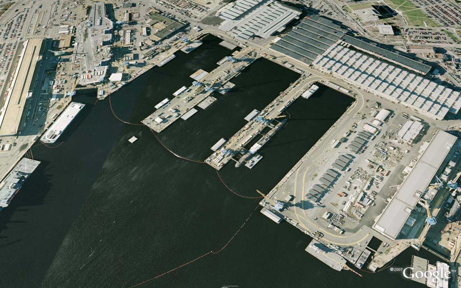
In June 2008, NAVFAC Mid-Atlantic, Hampton Roads Integrated Product Team (IPT), Norfolk, Virginia, announced its intent to award a Firm Fixed-Price, Stand-alone, Architect & Engineer (A-E) contract for Engineering and Design Services required for the Replacement of Pier 5 at the Norfolk Naval Shipyard (NNSY), Portsmouth, Virginia (Figure 1). The new pier design was required to accommodate all current and future Navy vessels, and includes a salt water pump station, restrooms, and heavy weather moorings. Crane rails and railroad tracks are required to accommodate repair operations. This project was part of the NAVFAC Fiscal Year 2010 Military Construction program and construction award was planned for Fiscal Year 2010, 2nd Quarter.
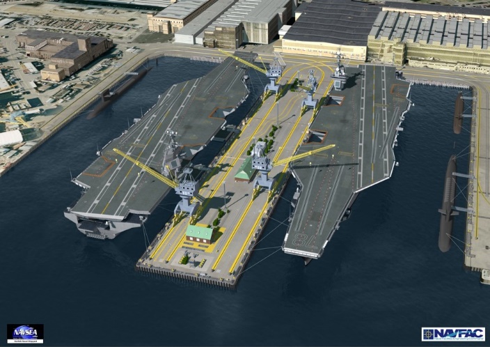
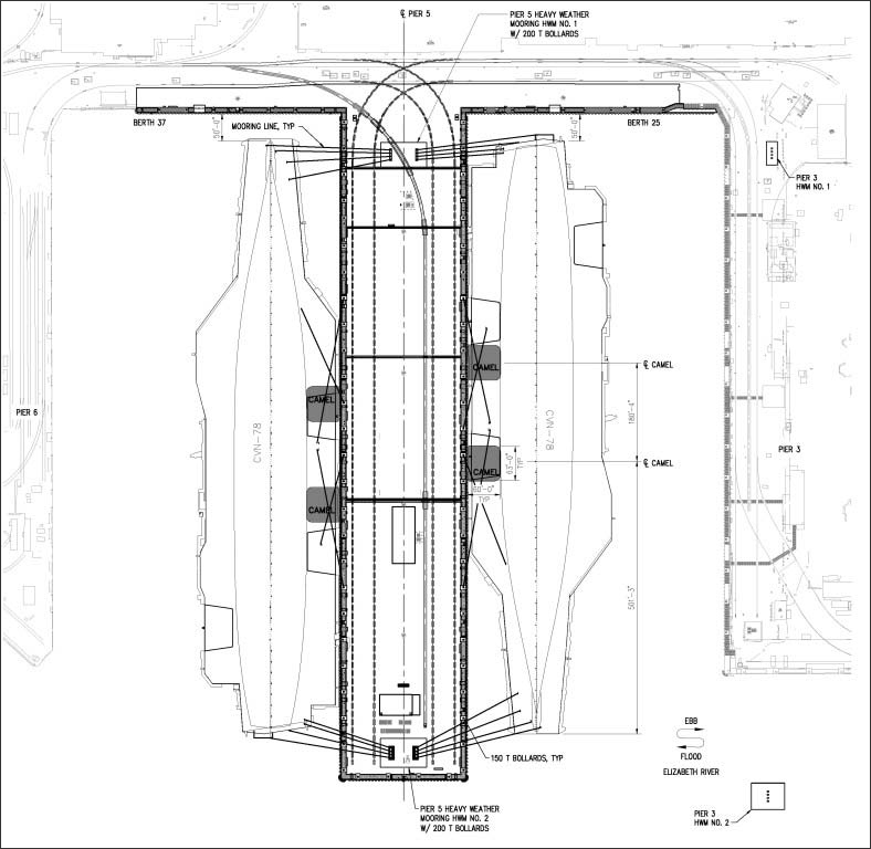
In April 2009, the Navy awarded a contract to design a replacement for Ship Repair Pier 5 at Norfolk Naval Shipyard to MN3M. The design involved the demolition of two 1,000-foot-long piers (Pier 4 and Pier 5) and five additional buildings to accommodate a new 1,225-foot-long, 230-foot-wide pier (Pier 5) supported by more than 1,200 36-inch precast, pre-stressed concrete cylinder piles (Figure 2). The pier features concrete bent caps, a low-level ballasted concrete deck, two heavy weather moorings with four 200-ton bollards, additional 150-ton bollards at 50-foot intervals, and a fendering system. The design also provided for the reconstruction of 1,000 feet of marginal wharf (Hitchcock Street), comprising a 180-foot-long, precast, pre-stressed concrete-pile-supported open wharf and an 820-foot-long, HP14 X 73 pile-supported closed-face wharf (Figure 3). Over 750,000 cubic yards of sediment was dredged from the berth area. Twin portal crane tracks and a railroad track were installed to support repair operations at the pier.
Mechanical systems installed at the pier include pure water, fresh water, salt water, steam, nitrogen, low-pressure compressed air, cooling, and flushing systems. The salt water system is essential for fire protection, and is managed at a new 12,000 GPM salt water pump station. Civil systems installed at the pier include storm water, sanitary sewer, and oily waste/waste oil collection systems. The pier is also equipped with primary and secondary power systems, high mast lighting, and a fiber optic communications network.
Final design of the project was delivered in February 2010, less than a year after contract award and $10 million under the Navy’s initial estimates for construction. In addition to the design, Moffatt & Nichol provided planning, analysis, rendering, design-bid-build contract documents, project management, and post-construction-award services. Moffatt & Nichol also created a state-of-the-art 3D model of the pier and wharf (Figure 2), the first time anything of its kind was undertaken for a Navy waterfront project.
Traditionally construction documents for offshore and waterfront projects have been developed using two-dimensional (2D) models with independent manually-created section, plan, and detail views. All material quantities used for estimation purposes are obtained through traditional quantity takeoff methods. This approach requires an extensive amount of review and coordination between disciplines to identify and mediate element conflicts and to verify that a consistent product is being portrayed throughout the construction documents. Combining the existing and new facilities proposed to support the repair operations at the pier involved the intertwining of structures, utilities, and complex mechanical and electrical systems. Such an effort would be very labor intensive using traditional design methods.
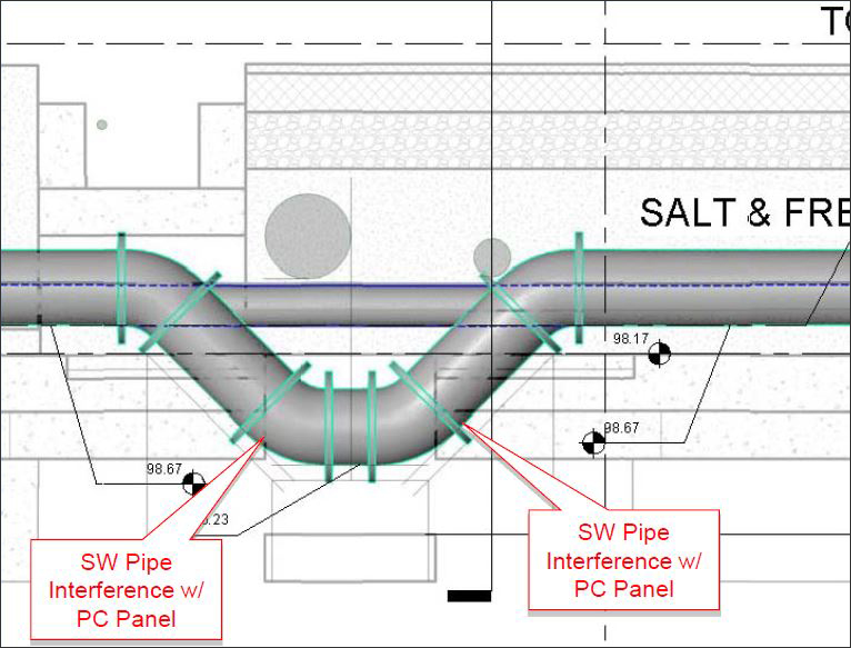
Early on in the design process, the project was humorously described as a pier and wharf to support utilities rather than ships. The mechanical, civil, power, and communication systems were designed to be installed in utility trenches and in the ballast of the pier (fill material between pier deck and top riding surface). Penetrations in the trenches were provided to allow the systems to transition between the ballast and the trenches. Using only 2D drawings in the past to identify locations in which systems conflicted with another had always been a difficult task. This was typically because the plan, section, and elevation drawings for each discipline were created independently from each other and then periodically reviewed during the design for consistency. Considering that it is not common for all of the design disciplines to work in the same location added an additional degree of difficulty to coordinating design changes between each group.
Just prior to the completion of the 35% Design for the project, the Navy asked the MN3M design team to consider developing a 3D Building Information Model of the project. The original intent was to have the model available for post-construction operation and maintenance of the pier. Recognizing the value the 3D model would provide during the design, the MN3M team agreed to immediately determine a suitable product and begin modeling.
At the beginning of the project, M&N had very little experience using BIM for this type of project, while other members of the MN3M joint venture had previously used BIM on projects involving vertical structures. Existing BIM packages offered products well suited for the type of elements typically found in vertical structures; however, very little was offered for the type of elements and systems intended to be used for this project.
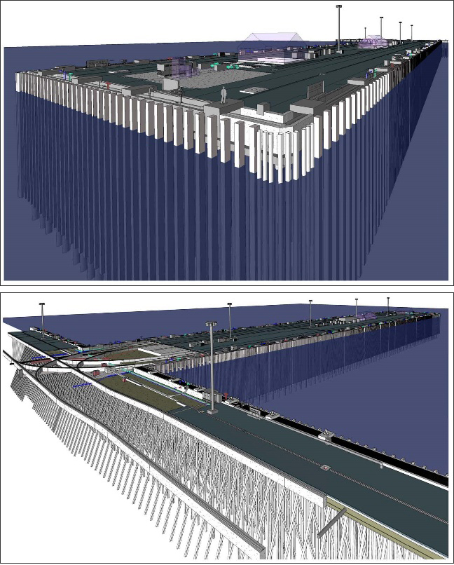
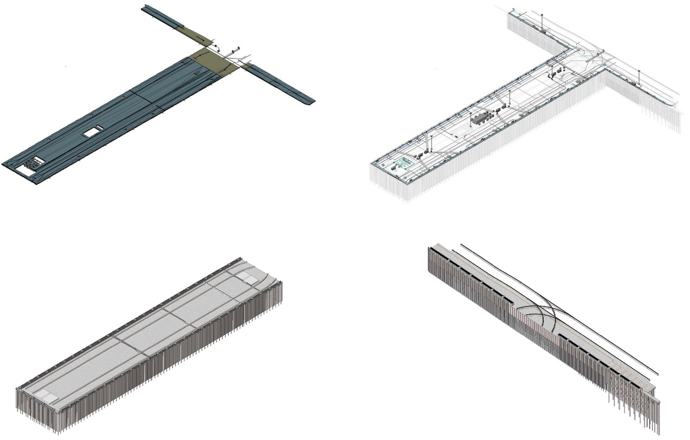
Construction documents were being developed using AutoCAD in accordance with the NAVFAC Computer Aided Drafting and Design (CADD) standards. Members of MN3M with BIM experience were using Autodesk Revit and its various families available at that time (Architecture, and MEP for mechanical electrical and plumbing). After researching the capabilities of BIM software packages, coordination with the design currently in production, and considering the software already being used, MN3M decided that the Autodesk Revit product would be the best option for developing the BIM model of the pier facility (Figure 4).
In August 2009, MN3M sent several designers to Advanced Training Center, Inc. (an Autodesk Authorized Training Center) in Cary, North Carolina, to receive training on Revit Structure 2010. The course was tailored to help develop the unique structural elements and systems required for this project. The course also guided the designers on how to successfully combine the different product families. The training established a great foundation for the development of the BIM model that was eventually created.
The work was divided up between MN3M based on disciplines. A Revit model was created for each discipline, and the structural discipline created a separate model for the pier and the marginal wharf (Figure 5). The model for the marginal wharf included all of the new elements to be constructed as part of the Pier 5 project as well as elements of the Pier 3 Replacement project (separate contract with construction occurring during design of Pier 5 Replacement), and all existing foundations and utilities within the vicinity of the portions of the wharf to be replaced. A majority of the existing elements were to be left in place, and this model was very helpful for designers in identifying potential conflicts with the new elements to be installed (Figure 7).
After the design was approved by the Navy, the Revit model was exported to a 3D AutoCAD model (.dwg file format). MN3M applied Uniformat II/Work Breakdown Structure (WBS) designations to all of the elements in the 3D AutoCAD model in accordance with the Whole Building Design Guide (WBDG) Performance Technical Specifications (PTS) as required by the Navy. The elements are categorized into one of nine sections:
All of the elements of this facility were categorized as Section H under the following subsections:
This 3D model will be used by the Navy as part of their asset management program by providing a way to account for each element of the facility.
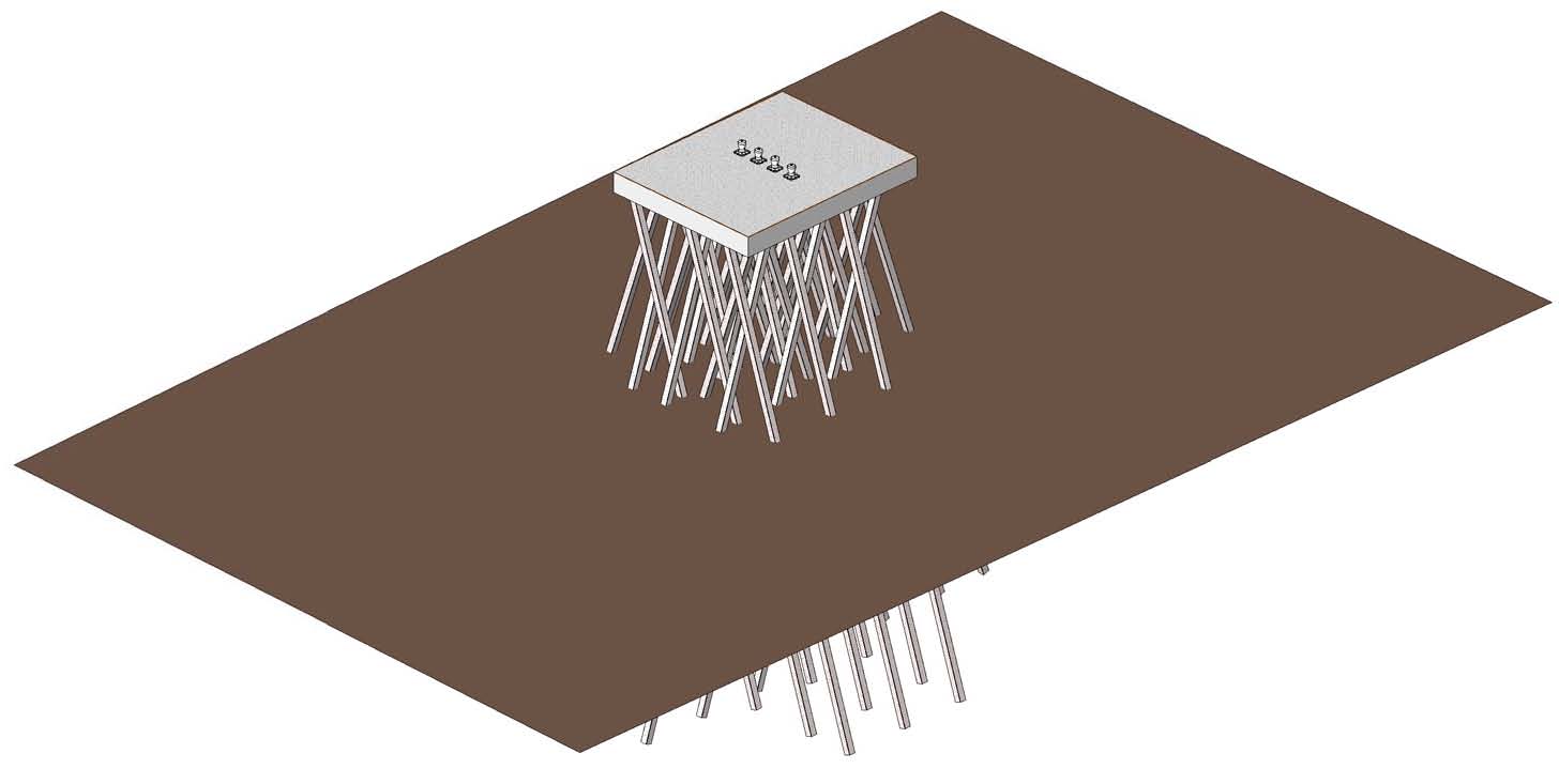
After the construction contract was awarded to Skanska USA Inc. (Skanska), a model of the Offshore Heavy Weather Mooring Structure (OHWMS) was developed to answer a Request for Information (RFI) submitted by Skanska (Figure 7). The model was developed to identify conflicts between batter piles and an existing mooring anchorage device located approximately 24 ft below the river bottom. A survey performed by Skanska identified the anchor’s location, the results were geo-referenced, and provided to MN3M. MN3M brought the survey into the Revit model. Two batter piles that would conflict with the mooring anchor per the original design were identified (Figure 8). These piles were relocated to a position that would not conflict with the mooring anchor or the other batter piles without compromising the intended structural capacity of the OHWMS.

Skanska also added a fourth dimension to the model during construction – time. This then enabled the Navy, Skanska and MN3M to visualize how the project would look during various stages of construction.
Throughout the design of the project, the MN3M team held biweekly meetings and exchanged AutoCAD files from each discipline. Incremental design submittals were provided to the Navy as follows:
A meeting between the Navy and the MN3M team was typically held within two weeks of each submittal. The exchange of information within the MN3M team occurred more frequently after the 35% Submittal as the Revit model was being developed. It was through the development of the Revit models that a majority of conflicts were identified. The Revit model was used at the Pre Final and Final Design meetings to help the Navy visualize the end product. This was particularly useful for meeting attendees that have difficulty understanding traditional 2D construction documents.
Overall, the use of BIM in this project provided a huge benefit to the designers and the client when compared to traditional 2D models. Despite not being used to develop the contract documents, the Revit model was very helpful when performing Quality Assurance (QA) reviews. All material quantities used for estimation purposes were obtained through traditional quantity takeoff methods as the cost estimate was started prior to the development of the Revit model; however, the Revit model was used to verify certain quantities.
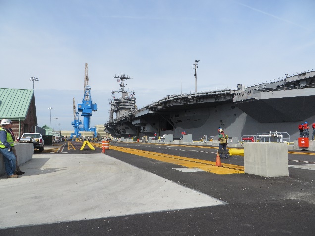
The north side of Pier 5 was accepted by the Government just prior to the docking of the United States Ship (USS) George H.W. Bush in November 2014. Construction of the complete project is scheduled for completion in the next few months (Figure 9).
M&N has since used BIM on several other major waterfront projects including:
 John E. Gaul was an employee with Moffatt & Nichol between May 2005 – August 2014. He has a Master’s Degree in Civil Engineering from Old Dominion University specializing in structural engineering, and is a licensed professional engineer in VA, MD, NC, DE, & FL. He served as a structural engineer on this project, and was heavily involved in the development of the Revit model. He currently is a project engineer at Pennoni and can be reached at jgaul@pennoni.com.
 Michael N. Rieger, PE, LEED AP is a Vice President and Business Unit Leader of Moffatt & Nichol’s Norfolk office. He served as the MN3M Project Manager for the Pier 5 Replacement project. He is a retired U.S. Navy Civil Engineer Corps CAPTAIN, serving over 26 years on active duty. He has a Master’s Degree in Construction Management from Purdue University and is a registered Professional Engineer in Virginia, New York, Georgia and South Carolina. He can be reached at mrieger@moffattnichol.com.
Have comments or feedback on this article? Visit its AECbytes blog posting to share them with other readers or see what others have to say.
AECbytes content should not be reproduced on any other website, blog, print publication, or newsletter without permission.