


This may seem to be contradictory, but Solibri Model Checker, the model-checking application for checking BIM models, actually pre-dates the term "building information modeling." I remember first being introduced to the application at an "Interoperability" workshop I attended in San Francisco all the way back in February 2001. The event was co-hosted by the Lawrence Berkeley National Laboratory and Pacific Gas and Electric, and it was used to showcase how the open-standards IFC file format could be used to link various analysis tools to the building information contained in an object-oriented CAD model—the term “BIM” hadn’t been introduced yet—to check different aspects of the design. Solibri Model Checker was one of the analysis tools that was demonstrated, showing how it could be used to check the building design for modeling errors, such as overlapping walls, as well as for design errors, such as insufficient areas or non-compliance of egress requirements.
A relatively new tool at that time, Solibri Model Checker (SMC) has since expanded its repertoire to include a much wider range of capabilities in addition to model-checking, including multi-disciplinary coordination, clash detection, model comparison, quantity take-off, and issue management. The argument for an application like this was so compelling that SMC was acquired by the publicly traded Nemetschek Group in 2015 and added to its growing portfolio of leading AEC technology applications including Allplan, ARCHICAD, Vectorworks, Scia, Bluebeam, and dRofus, all of which communicate and work together through the IFC. Since SMC was developed to work with the IFC format from the start, it fits right in with the OpenBIM philosophy of the Nemetschek Group.
It has been over six years since I last reviewed SMC, and while model-checking is still the raison d'être of the application, it has so many enhancements to its interface and functionality that this review takes a step back and looks at it from scratch to see how it works.
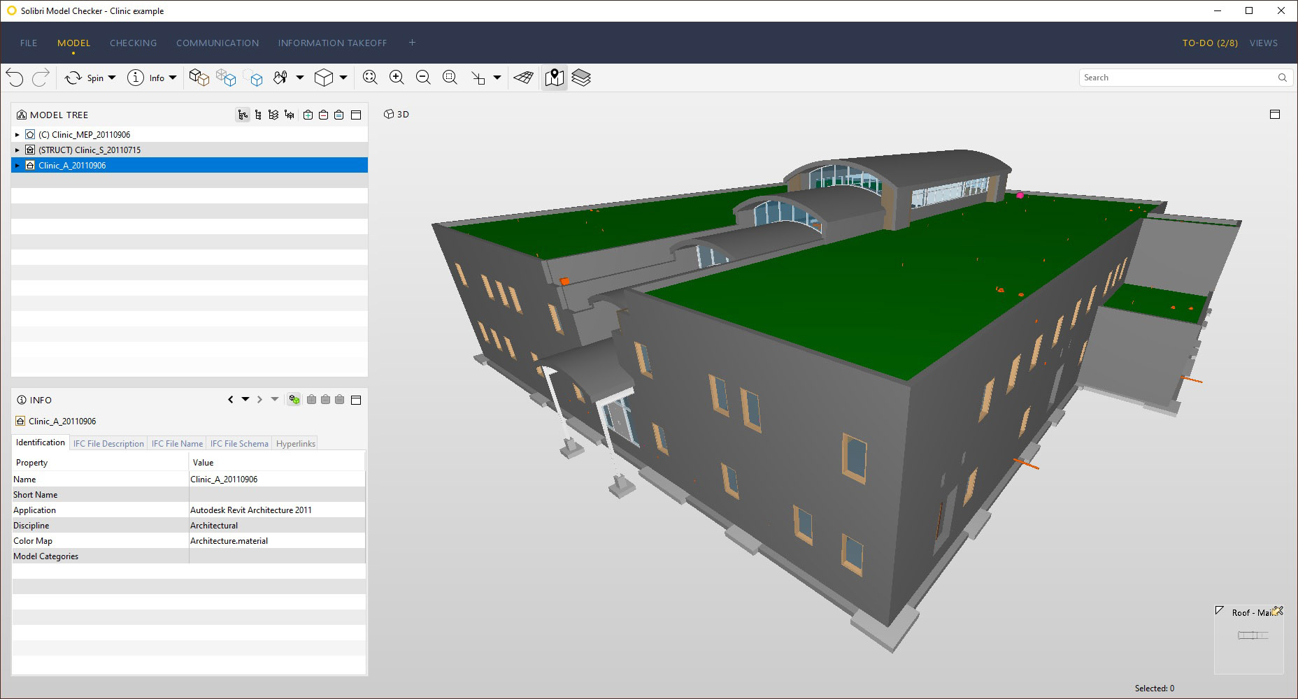
The starting point for SMC is a building model created in an IFC-compliant application and saved in the IFC format. This model can then be opened in the application and subsequently saved in the SMC format, which is much smaller than both the native file size as well as its IFC version. You can also bring in multiple IFC models—for example, different disciplinary models of the same building—and save the combined model in one SMC file to achieve the same compression benefits in addition to being able to coordinate the models. For example, Figure 1 shows an SMC file that combines the architecture, structure, and MEP models of a building project, all of which were originally created in Revit.
When an IFC file is first opened in SMC, the application asks you to confirm the discipline the model belongs to. This is important for the rules to work correctly when checking the model later. In the case of the models shown in Figure 1, they were correctly identified when first imported.
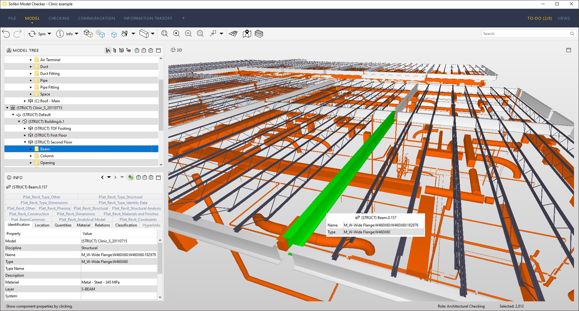
Once the models are in SMC, they can be explored with an extensive set of navigation tools to better understand how the different components of the building come together, and visually inspect the design to spot any coordination problems even prior to getting into the model-checking process. There are the usual Zoom, Pan, Spin, and Walk tools; a Game mode that allows you to walk inside the building using typical gaming controls; and a Sectioning tool to explore the interior of a model. The Model Tree can be viewed in three different ways: by containment, by object types, or by layers. Double-clicking on any element or category of elements automatically zooms the view to the selection. The visibility of entire models, levels, or specific elements can be turned off or set to transparent, making it easier to explore different parts of the model in context with other elements (Figure 2). Detailed information about a selected element is displayed in the Info palette, and as shown in Figure 2, the selected beam from the imported Revit model maintains the properties assigned to it in Revit.
Additional model-related capabilities include the ability to add markups, measure distances, and import drawings that can be overlaid with the models for easy comparison (Figure 3). Also, while the IFC file format is the main entry point to SMC, it does have direct integration with ARCHICAD through a custom link which allows an ARCHICAD model to be directly exported to SMC for design checking (Figure 4). If any faults are detected in SMC, the corresponding elements can be highlighted in ARCHICAD where the necessary corrections can be made.


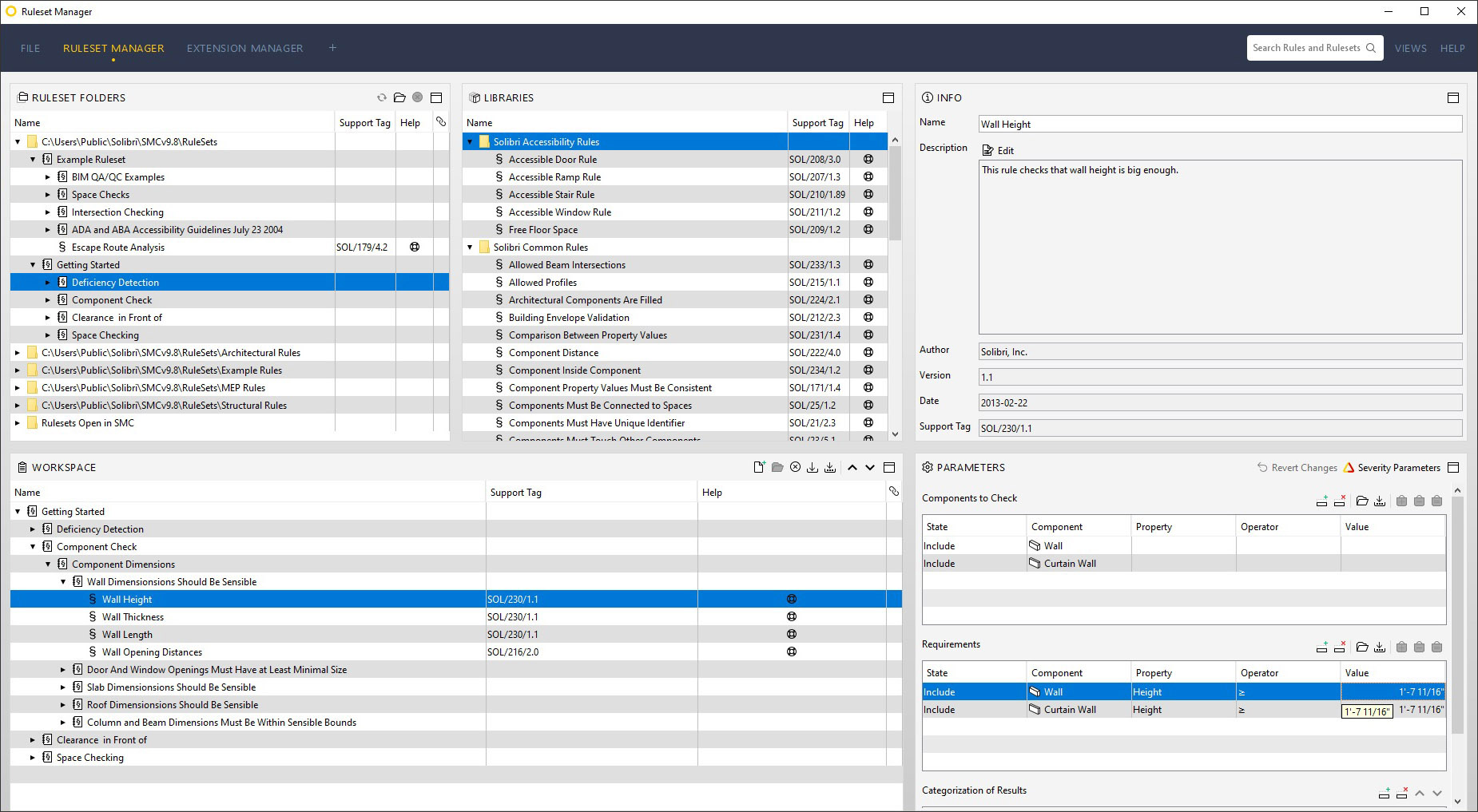
The checking functionality of the application can be accessed by going to the Checking tab. Here you would load the “rulesets” that you would like to use for checking the model. A ruleset is essentially a collection of rules, and SMC comes with a large number of rulesets for checking different aspects of the design, for each individual discipline as well as for the building as a whole. There is a dedicated Ruleset Manager interface where you can browse through the different rulesets and the individual rules comprising each ruleset. As shown in Figure 5, you can browse through all available rulesets by specifying the location of the Ruleset Folders as well as browse through all the individual rules that come with the application in the Libraries panel. The details about a selected rule or ruleset can be seen in the Info panel. There is a dedicated Workspace area for creating a new ruleset from the available rules or for editing an existing ruleset. The editing process allows you to change the parameters of specific rules to configure them to fit project-specific needs. For example, Figure 5 shows a rule for Wall Height—which is part of the Getting Started ruleset that has been opened for editing in the Workspace panel—selected, so that its parameters can be viewed and modified, if required, in the Parameters panel. The ruleset structure is hierarchical, which means there can be multiple levels of rulesets comprised of other rulesets, with the final tier being the individual rules at the base of the ruleset structure, as in the example shown in the Workspace panel in Figure 5.
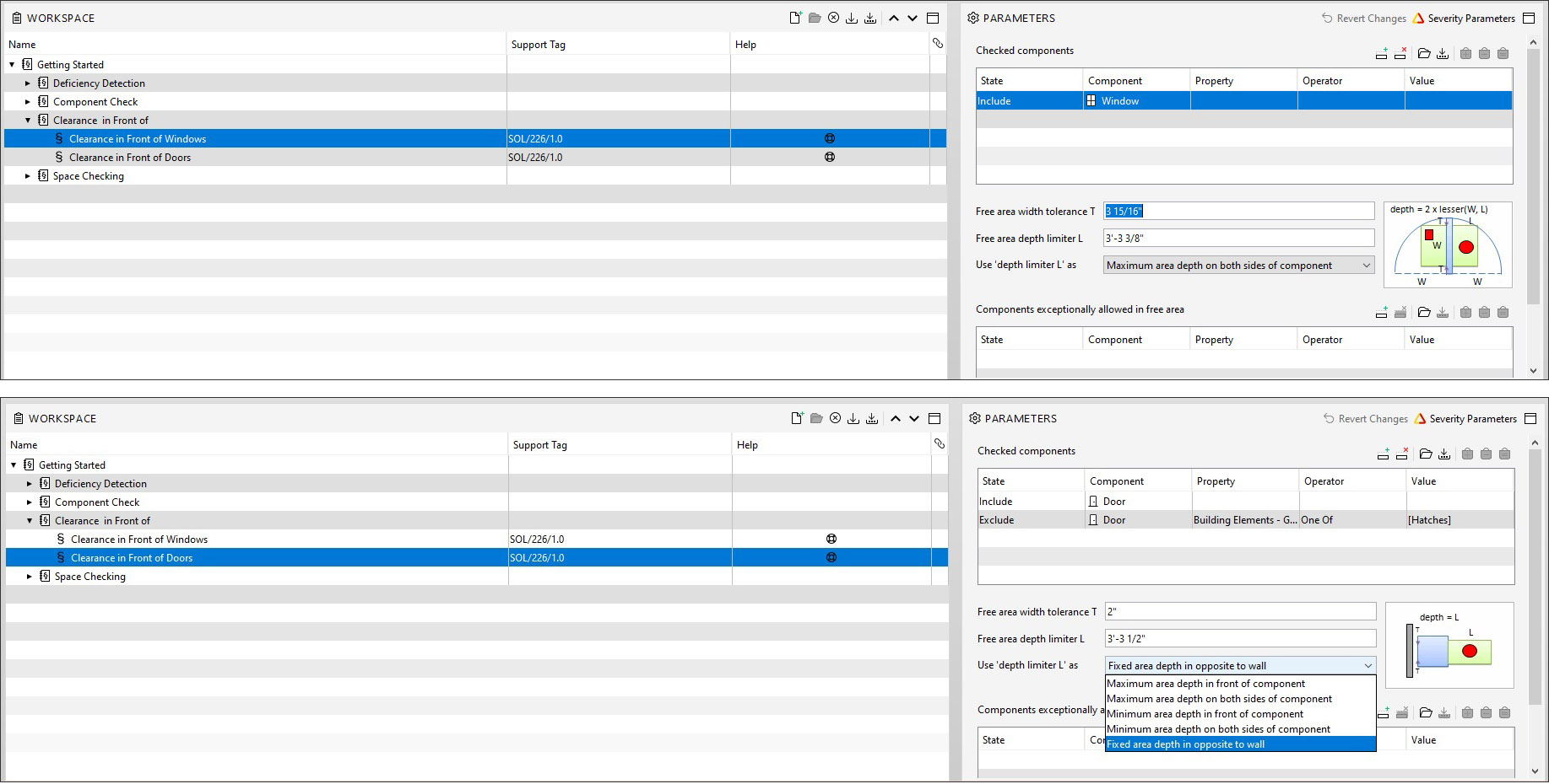
While the example of the rule being edited in Figure 5—the Wall Height—was a simple one, many of the other rules have parameters that are quite involved. Two examples are shown in Figure 6, one for “Clearance in Front of Windows” and the other for “Clearance in Front of Doors,” where you can specify exact clearance values that the model will be checked for when these rules are activated. Other examples of rule parameters that can be modified include the minimum and maximum dimensions of components such as walls, slabs, beams, and columns; the ratio of the window area to the floor area of spaces; the maximum allowable distance of any space to the nearest exit when checking for valid escape routes; the allowable overlaps when checking for intersections between any two types of components; checking if there are enough parking spots for disabled people in a parking lot; and so on.
Back in the model, you can select the rulesets you would like to use to check the model. For example, Figure 7 shows the Getting Started ruleset being activated to check the model. After the checking process is completed, you can drill down to the results for each rule to find out whether it passed or failed, and with what level of severity as indicated by the various icons. All the individual results for a rule are listed in the Results window, and clicking on a result automatically zooms in to the related element in the graphics window, enabling the results to be more closely inspected. The results can also be exported to a report in PDF or Excel format.

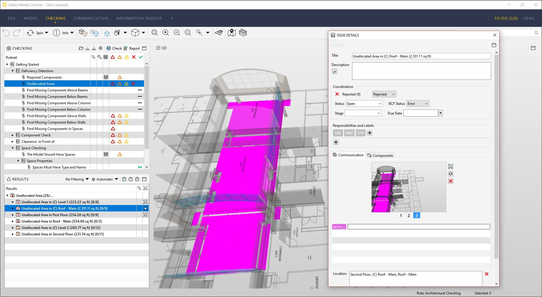
There are some additional options available by right-clicking on any of the results in the Results window, including marking it as accepted or rejected, creating a section box around it, creating a hyperlink to it for easy access, and most importantly, being able to record it as an issue as shown in Figure 8. In addition to the details about the issue, you can capture multiple graphical views of it in the form of slides. For example, the issue created in Figure 8 has three views.
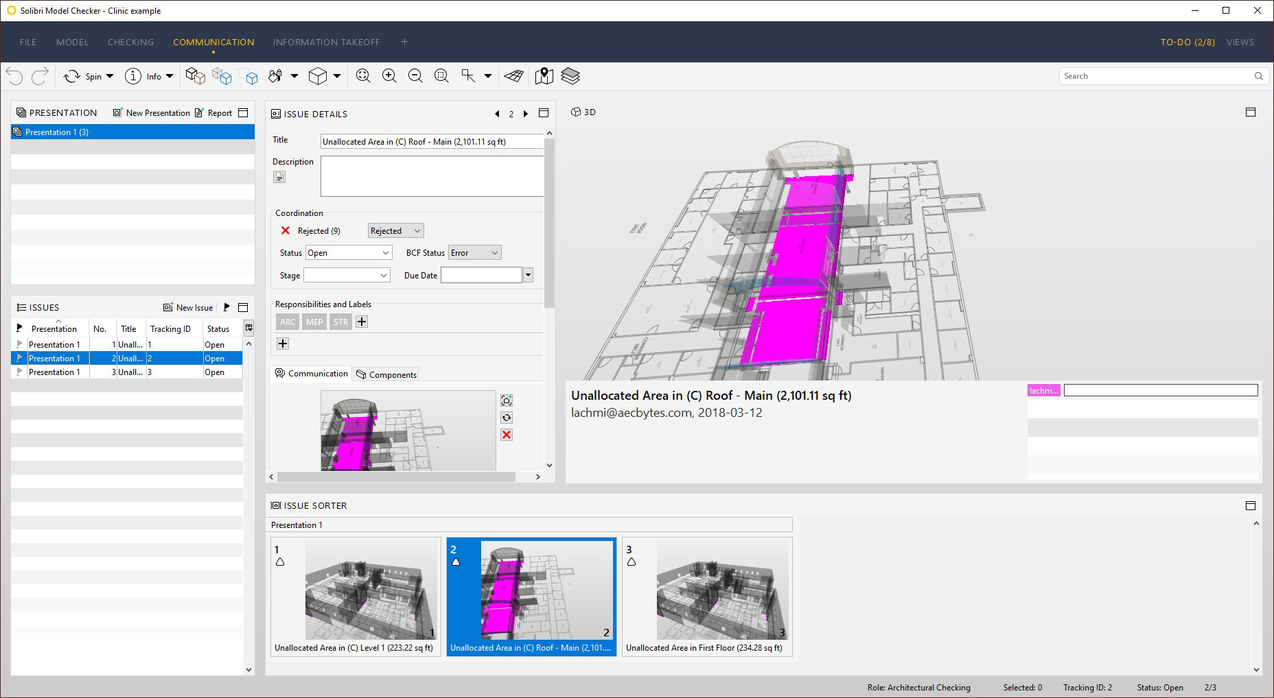
If you now go to the Communication tab, you can choose to create a presentation of all the checking results, and as shown in Figure 9, the issue that was created in Figure 8 is created as an individual slide in the presentation. These slides will automatically be created from all the checking results that were recorded as issues. It is also possible to add markups and other annotations to the views if required.
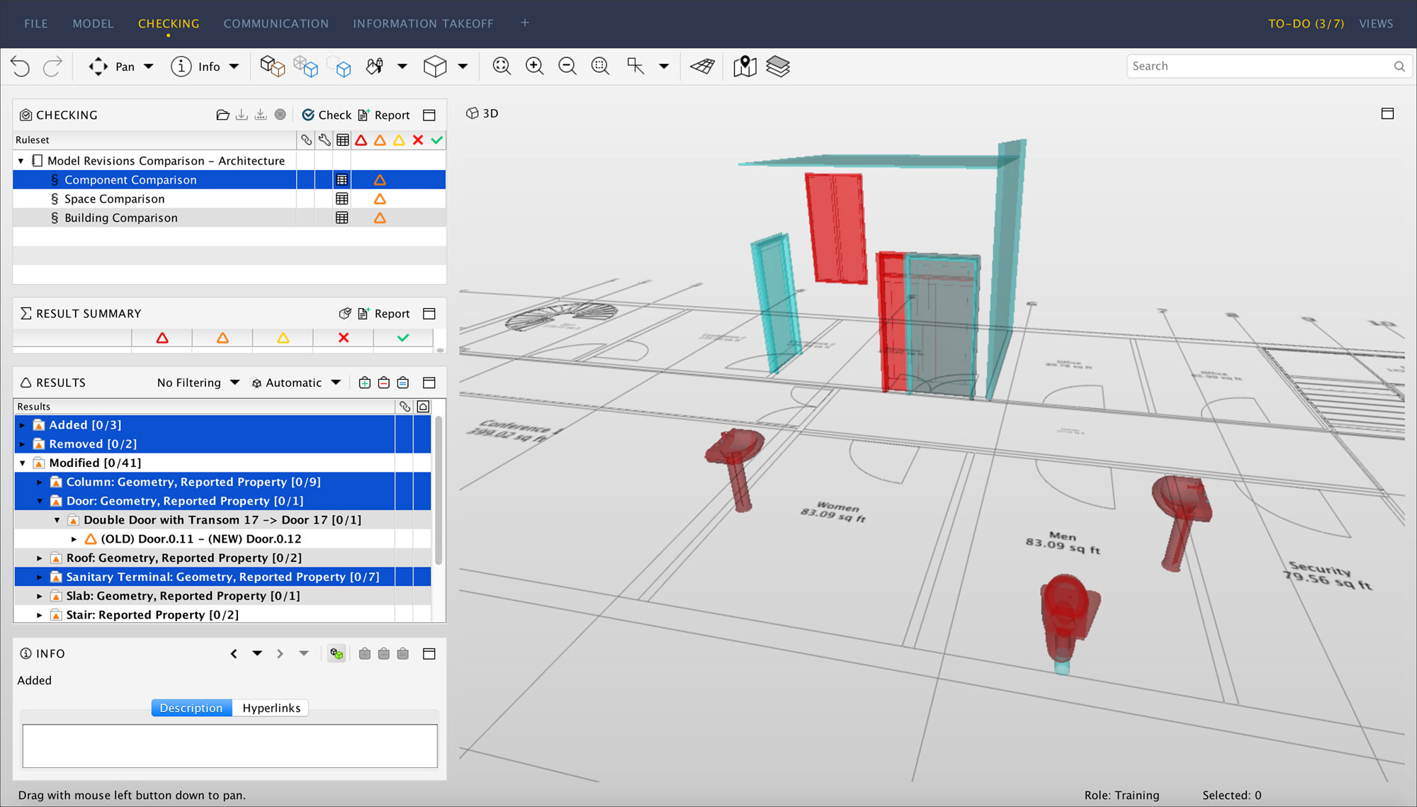
The presentation can be saved as a report in a format such as PDF or Excel to share with other team members. It can also be exported in the open BCF format (BIM Collaboration Format) that is supported by many BIM authoring and analysis applications. With Solibri's BCF Connector, issues can be synchronized to issue management platforms such as BIMcollab for exchanging IFC models annotated with comments, markups, etc., for collaboration. Based on the issues identified in SMC, the necessary fixes can be made in the original authoring applications of the individual models and they can be updated in SMC with the newer versions. Decisions, snapshots, and comments stay unchanged for those parts that have not been affected by the update. It is also possible to color-code the changes to see them more clearly using a dedicated Model Revisions Comparison ruleset, as shown in Figure 10.
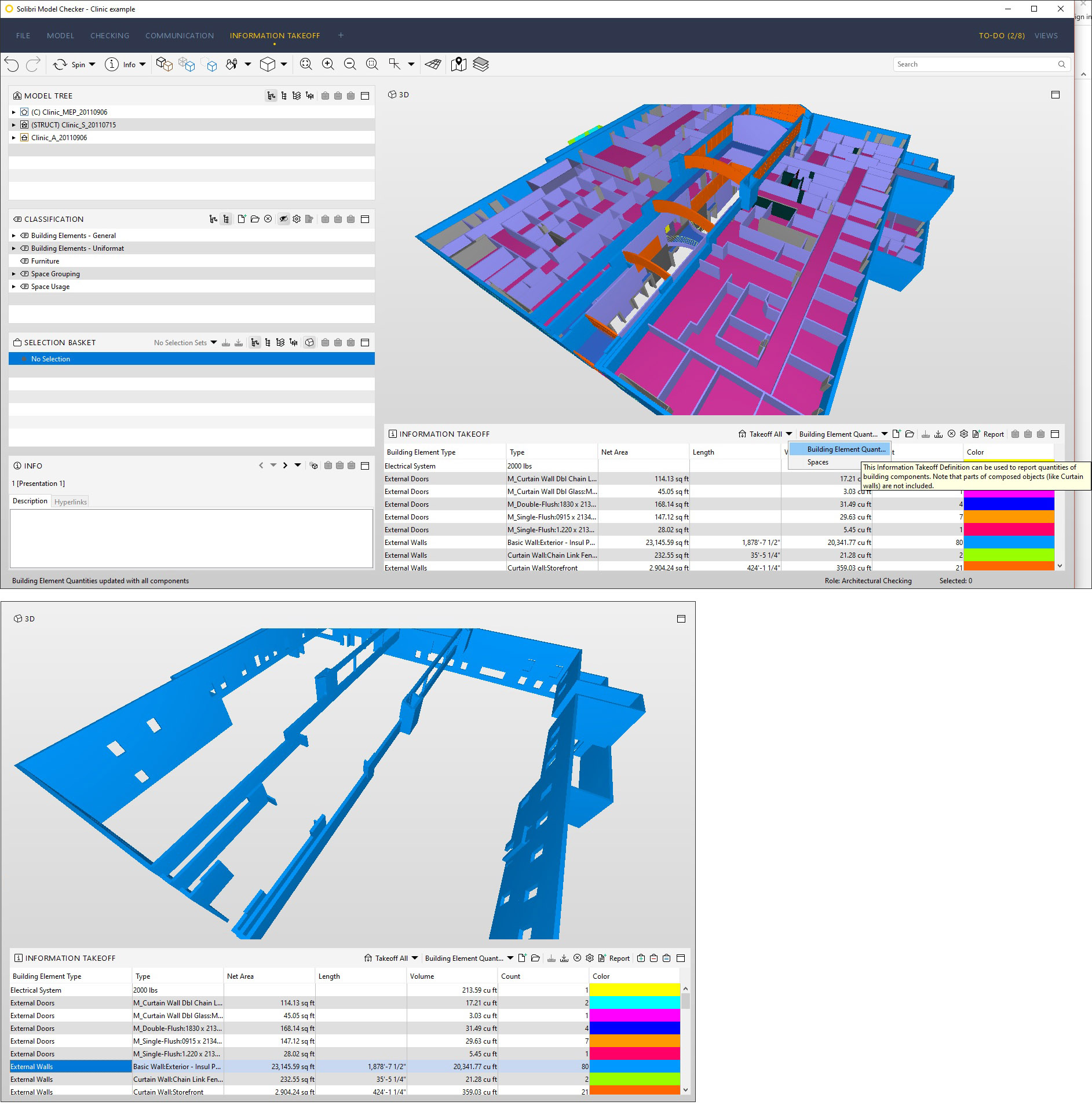
In addition to model-checking, collaboration, and issue management, SMC provides the ability to collect quantity information from the BIM model and export it to an estimating application. This is done using the Information Takeoff interface shown in Figure 11, where an Information Takeoff Definition called “Building Element Quantities” is applied to the entire model. The results are listed in the Information Takeoff panel with the quantity and dimension information for each category and type of element, along with the color that is used to display that element type in the graphics window. The color can be customized as required. Each category can be inspected in more detail by selecting it from the Information Takeoff list, such as in the lower image of Figure 11, where a particular type of Exterior Wall has been selected. The display of all the other elements in the model is hidden.
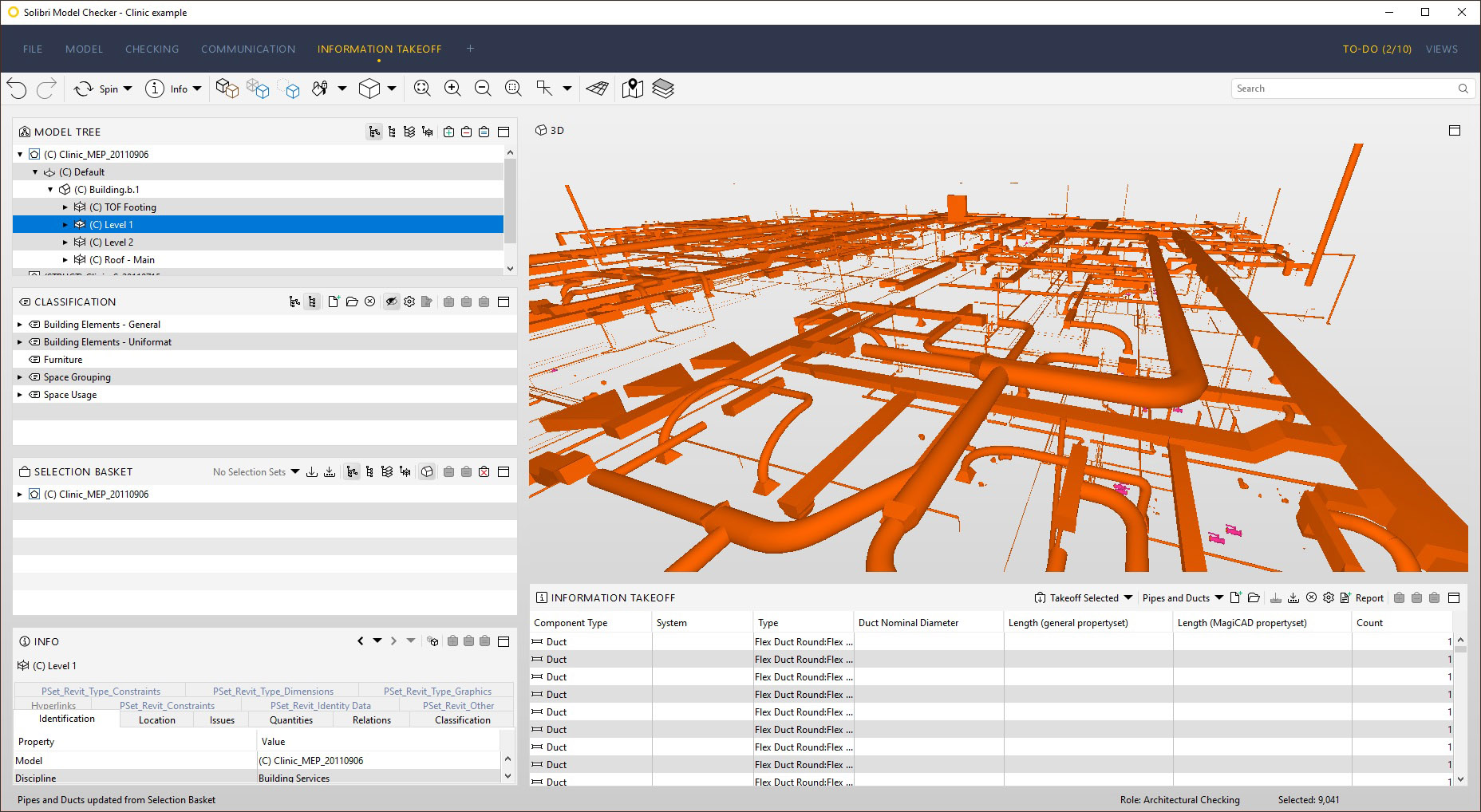
In addition to customizing the color display of a category, you can also add and edit columns in the Information Takeoff table, sort the results by a specific column, rearrange the columns, and so on. You can report the results for further analysis by exporting the report in Excel format. It is also possible to determine exactly what information gets taken off from the model by choosing a different Information Takeoff definition and restricting the takeoff to specific elements selected in the Model Tree. For example, Figure 12 shows an Information Takeoff of “Pipes and Ducts” applied to only Level 1 of the MEP model of the building project.
There are several sample Information Takeoff definitions that are delivered with the application, and additional ones can be created, if required. Just as with any other custom creations such as rulesets, these custom definitions can be shared with other project team members or used on other BIM models to ensure consistency.
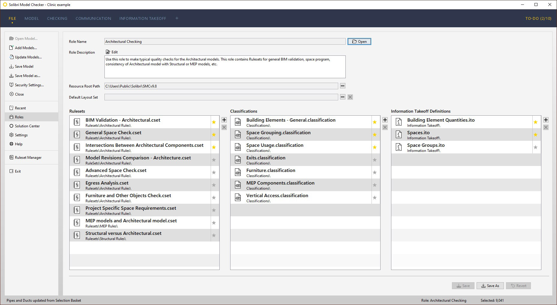
An additional aspect of SMC is the ability to define “roles” for the different disciplinary professionals who will need to work with the application. Each role has specific Rulesets, Classifications, and Information Takeoff definitions associated with it, which become available once a role has been selected. For example, Figure 13 shows the rulesets, classifications, and Information Takeoff definitions associated with the role of “Architectural Checking” that has been selected. The ones that are marked by a yellow star are those that will automatically be opened when you open a new file. Role can be selected from the list of pre-defined roles that Solibri provides, but firms can also create their own roles or modify the pre-defined ones to better suit their workflows and processes.
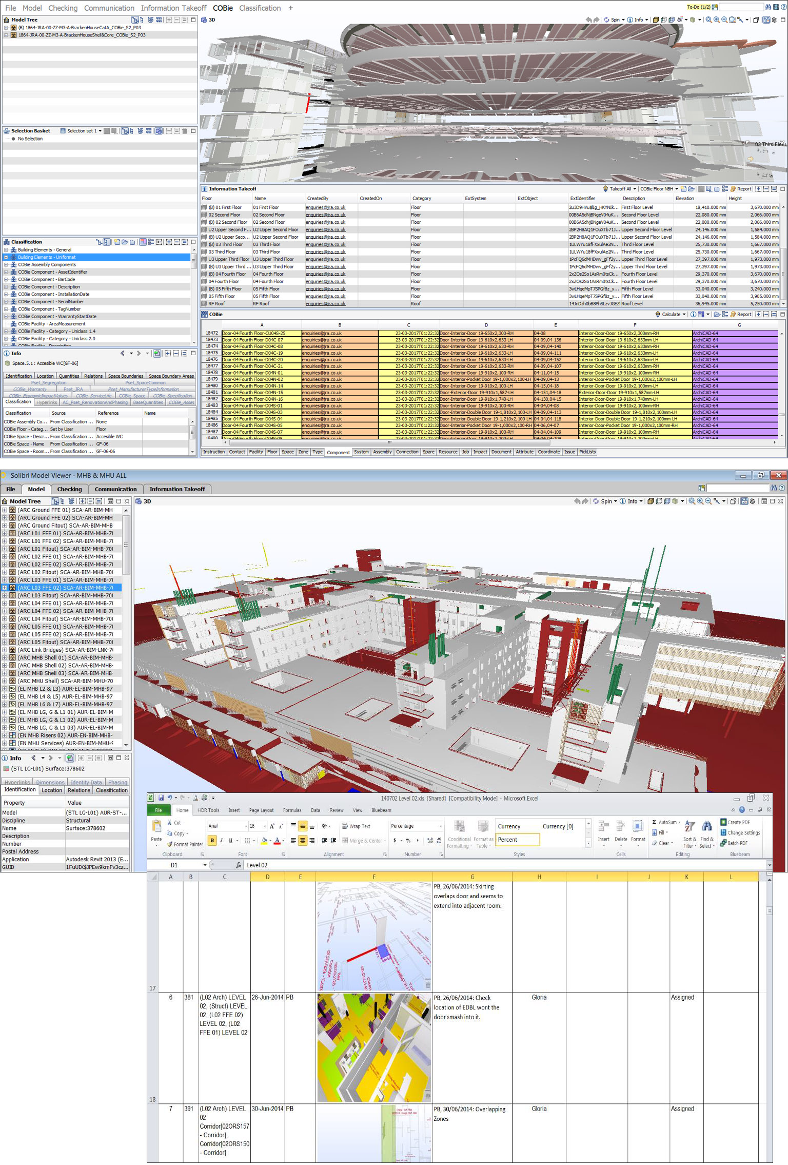
As I mentioned in my recent article on GRAPHISOFT’s KCC 2017 conference, the use of SMC was almost universal among the firms from all over the world who presented at the conference, including design as well as construction firms, who used it for model aggregation and review, multi-disciplinary coordination, clash detection, quantity take-off, and issue management. Two examples that were showcased are illustrated in Figure 14, one from the London-based firm, John Robertson Architects, and the other from the Australian firm, HDR Rice Daubney.
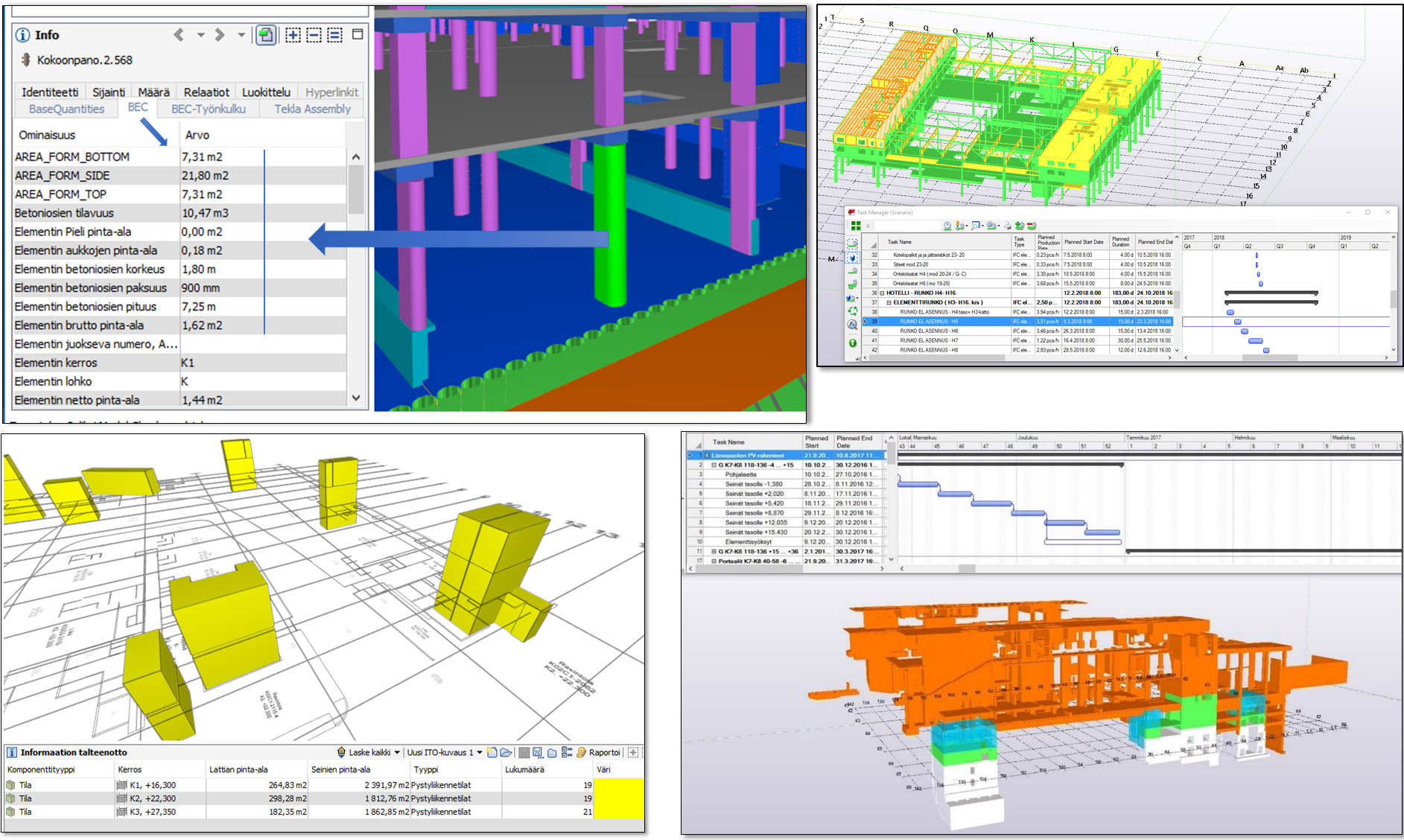
The global reach of SMC is also highlighted by additional implementations such as its use on the largest development project in Finland to date called Tripla (Figure 15). This is located three kilometers from downtown Helsinki and includes apartments, offices, hotel, the biggest shopping center in Finland, a public transport terminal, pedestrian and bicycle paths, parks and squares, and underground parking space. Currently under construction, it is expected to be completed by 2021. More than 20 parties are involved in designing this project, and all the designers are modeling with BIM, which means that several design phases were done in parallel and the size of the BIM models are enormous. IFC files that are produced from all design disciplines are brought together in SMC regularly, allowing a merged BIM model to be created from, in this case, 72 separate BIM models and 300, 000 objects. In addition to model aggregation, SMC is also being used for information management, quantity takeoff, export to scheduling applications, and 4D visualizations (Figure 16).

Getting back to that interoperability workshop I attended in 2001, SMC was way ahead of its times, and even in my 2011 review, a full ten years later, I wondered why its use was not much more widespread and commonplace, given that it was the only application that was available for checking the soundness and integrity of BIM models.For several years prior to that, it seemed as though the application was poised to take off for automated code-checking, with initiatives such as the SMARTcodes project to automate BIM-based code compliance in the US around 2005 and Autocodes, a more recent initiative. However, the SMARTcodes project has since been discontinued and while Autocodes still seems to be alive, there doesn’t seem to be much activity around it. Thus, while the use of SMC for government-driven automated code-checking seems to have been stalled—given the lack of progress in that field—it is interesting to see the growing use of SMC by individual AEC firms all over the world to improve their own BIM processes.
I would say that Solibri Model Checker has finally come into its own.
Lachmi Khemlani is founder and editor of AECbytes. She has a Ph.D. in Architecture from UC Berkeley, specializing in intelligent building modeling, and consults and writes on AEC technology.
Have comments or feedback on this article? Visit its AECbytes blog posting to share them with other readers or see what others have to say.
AECbytes content should not be reproduced on any other website, blog, print publication, or newsletter without permission.