


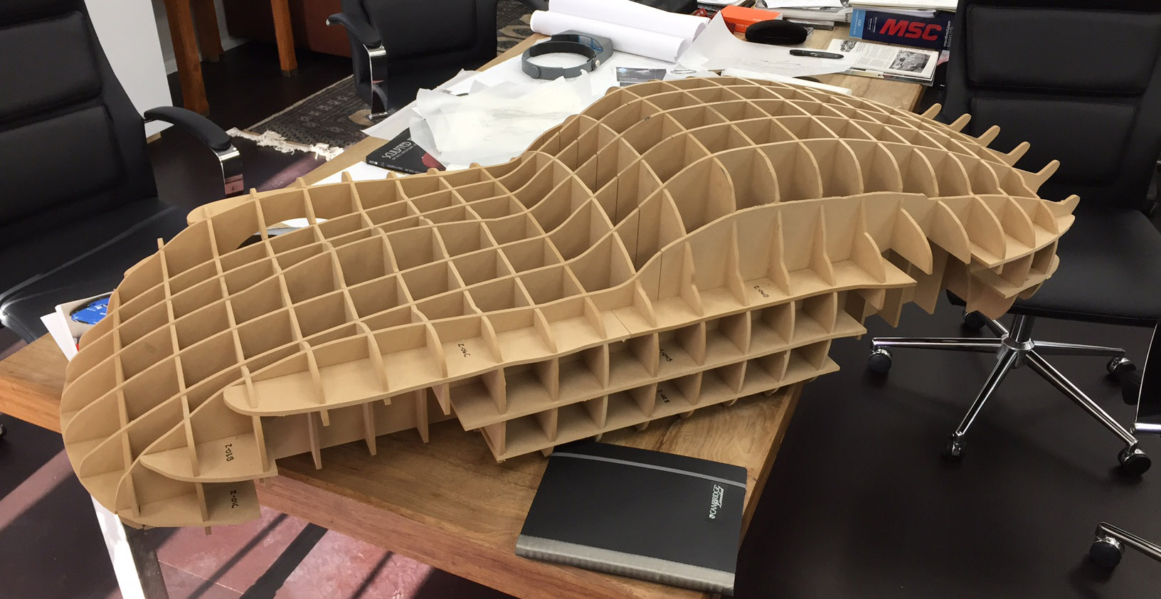
From a structural perspective, a waffle slab in a building is typically used for covering large spans without a column, and it can carry a heavier load than a flat slab. Over and above this, however, a waffle structure also lends itself to construct complex, organic forms much more easily than other types of structures, not just in architectural design (Figure 1) but also in industrial design (Figure 2).

To create a computer model of a waffle structure, any NURBS-capable application will work, but the application that is most commonly used is Rhino. While the structure can be entirely modeled in Rhino, the use of Grasshopper—a graphical algorithm editor tightly integrated in Rhino—makes it much more powerful and allows design changes such as the spacing of the ribs and their thickness to be made much more quickly and easily.
This tutorial walks you through the steps for modeling a waffle structure in Rhino using a Grasshopper script. It assumes some familiarity with Rhino and a basic knowledge of the Grasshopper interface.
We will start by first modeling the waffle structure entirely in Rhino, showing how it is less forgiving of design changes as it requires a complete manual re-creation of the ribs of the structure every time a change is made.
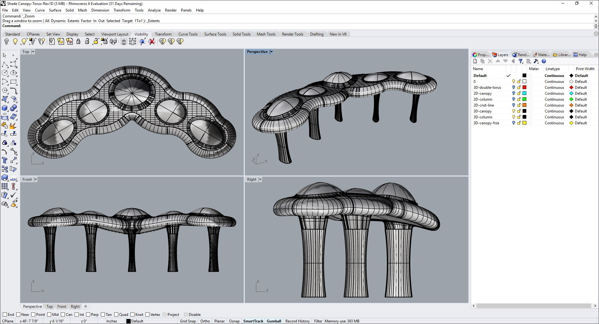
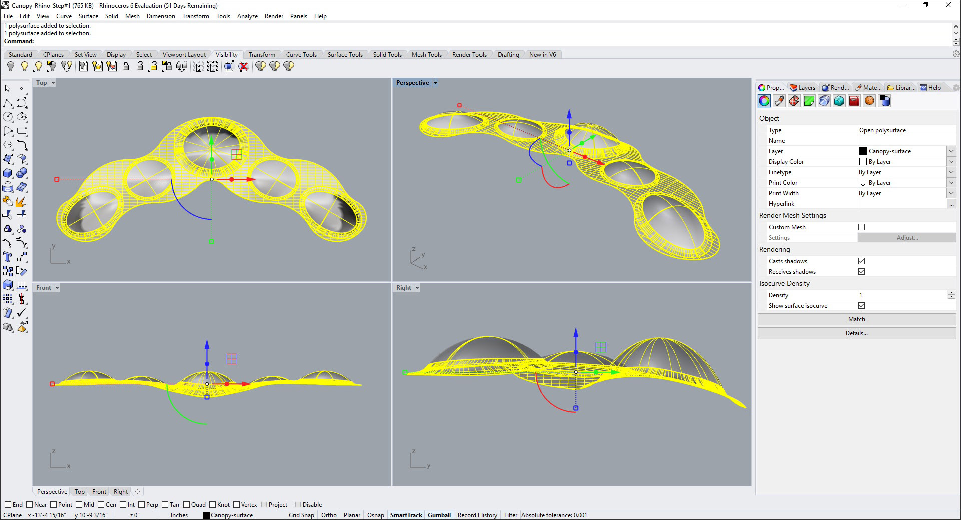
Figure 3 shows the massing model of a canopy design, the top of which we want to construct as a waffle structure. Figure 4 shows just the top surface which has been copied to a separate file.
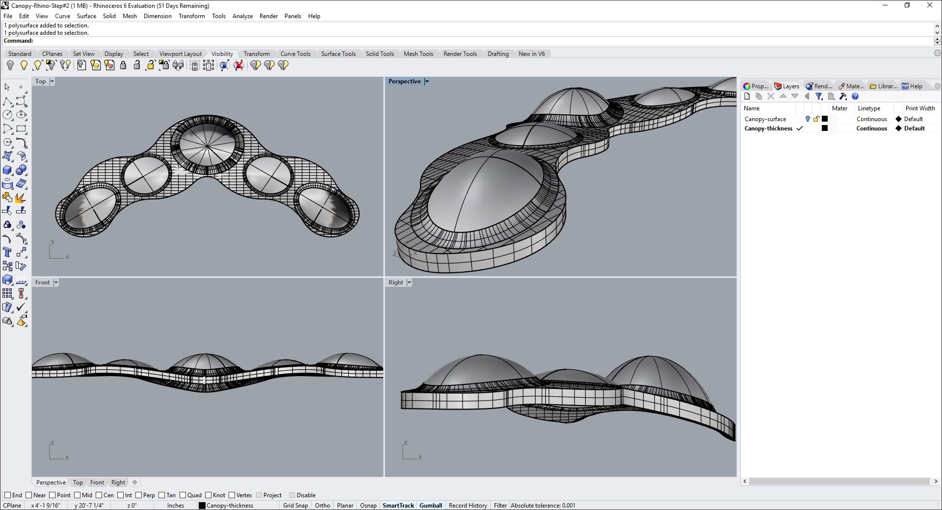
Next, the surface has to be given a thickness that is equal to the depth of the waffle structure. This can be done by creating a copy of the surface, using the Loft tool to connect the edges, and finally joining all the surfaces together to form one object (Figure 5).
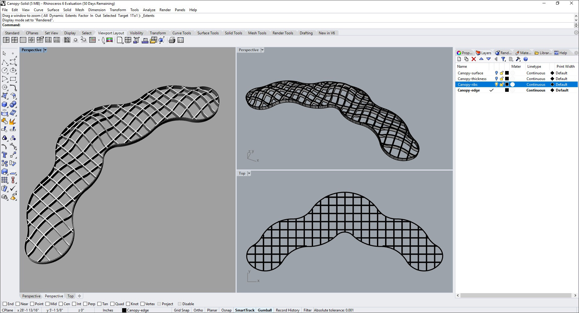
The next two images show the use of the Contour and Extrude commands in Rhino to create the ribs of the waffle structure at a specified spacing and using a specified thickness.
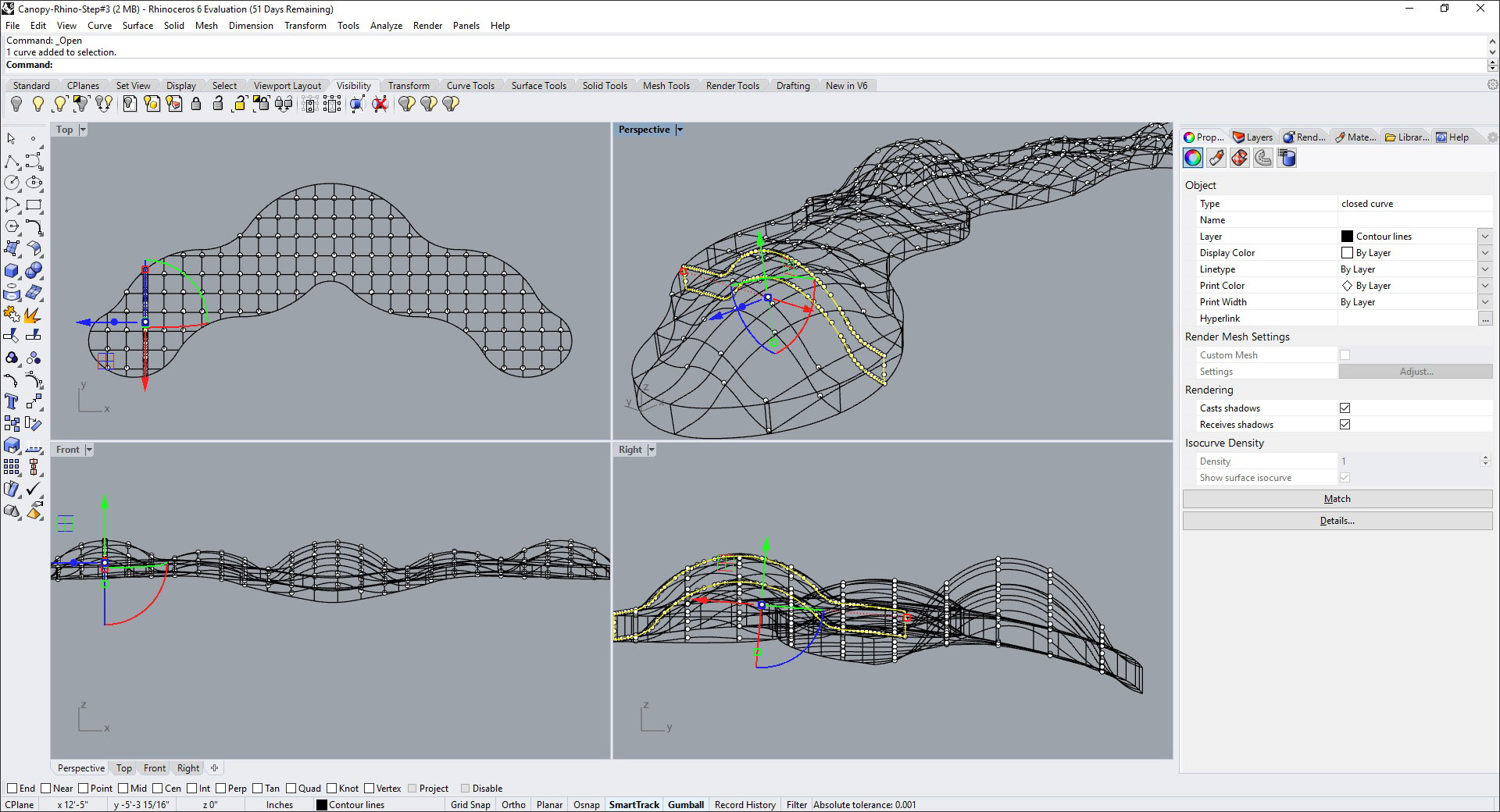
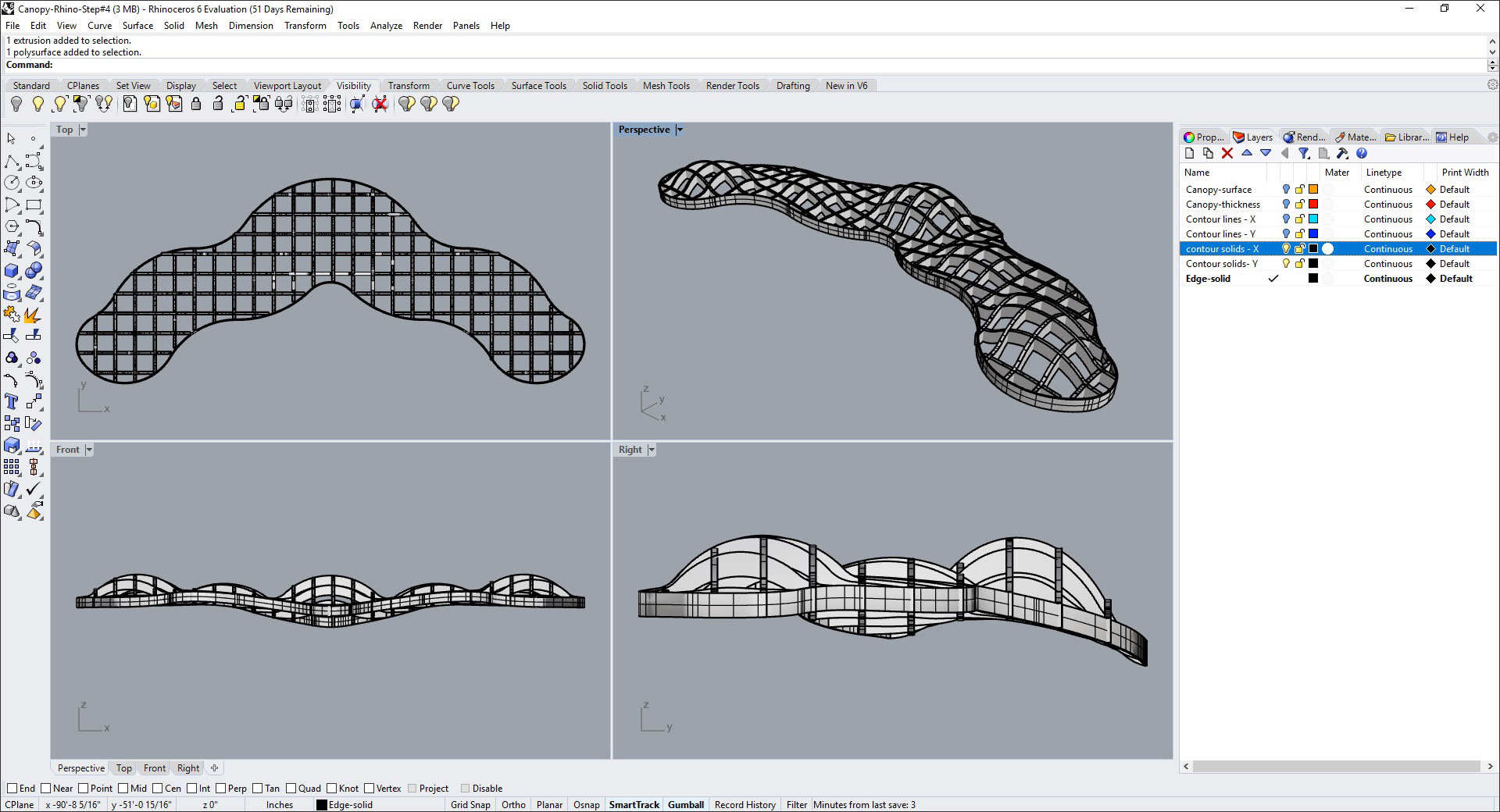
While this may seem a perfectly good way to model a waffle structure in a 3D modeling application, we can achieve a lot more flexibility in the spacing of the ribs and their thickness using a Grasshopper script. The rest of this tutorial will demonstrate the step-by-step creation of the script.
Our starting point for the Grasshopper script is the Rhino model of the surface with the thickness that was shown in Figure 5, prior to the application of the Contour and Extrude tools to create the ribs for the structure. This will be referred to as the “canopy object.”
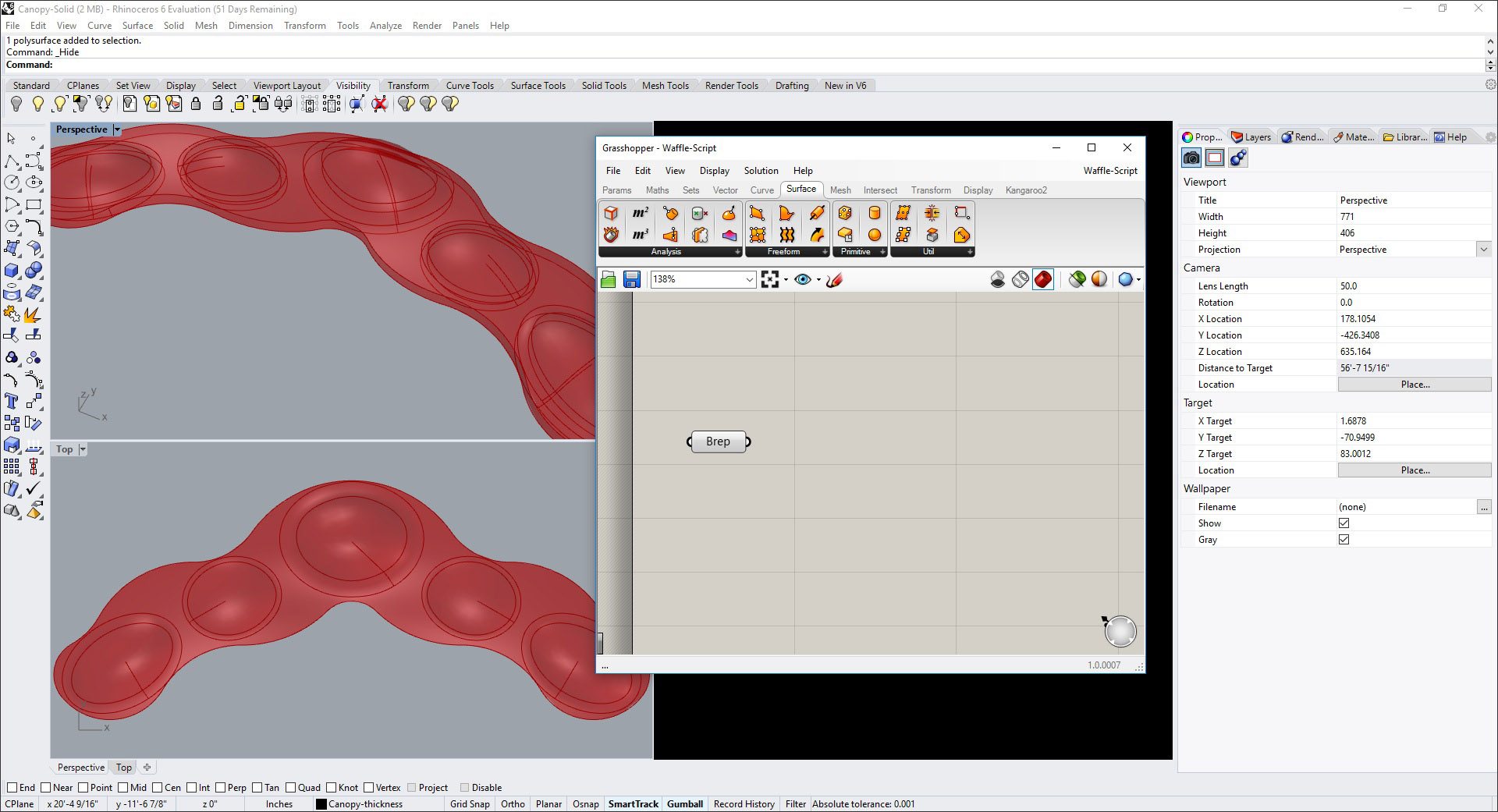
With the Rhino model of this canopy object open, go to the Tools menu and open Grasshopper. It will open in a separate window that is overlaid on the Rhino window. Start the script by creating a Brep (boundary representation) component.
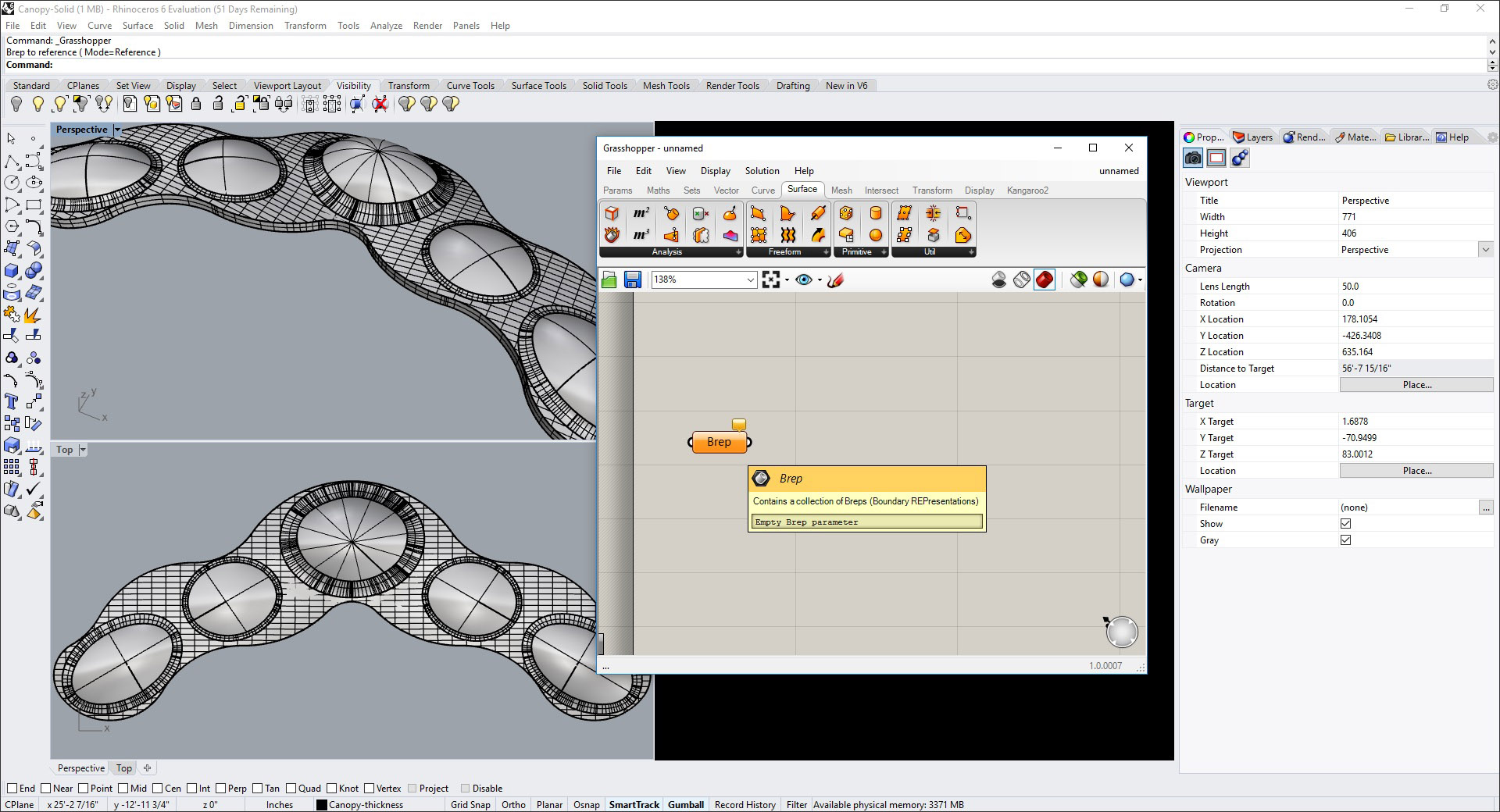
Connect this Brep component in Grasshopper to the canopy object in Rhino by selecting the Set one Brep command from the right-click menu and selecting the Rhino object. All the scripts connected to the Brep component in Grasshopper will now be applied to the selected Rhino object. So far, we have not created a script yet, so there is nothing to see except an indication that the Rhino object has been set as the Brep.
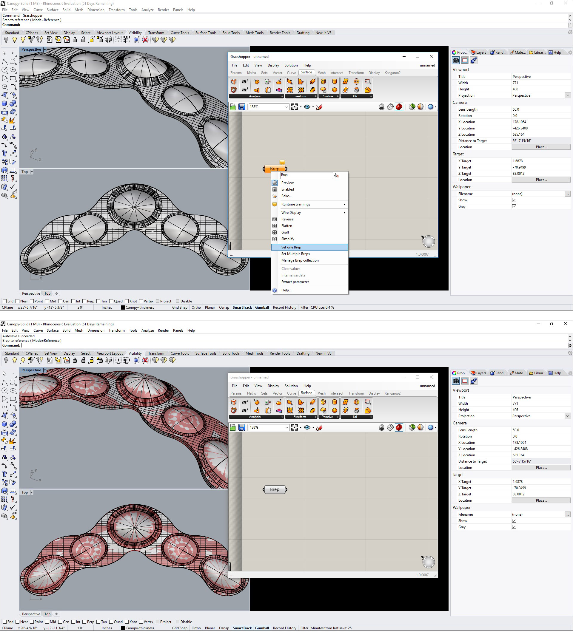
Since the Grasshopper file is different from the Rhino file—which allows the script to be applied to multiple Rhino files and vice versa—make sure you save the script file.
You can hide the Rhino object to make the results of the script more visible.
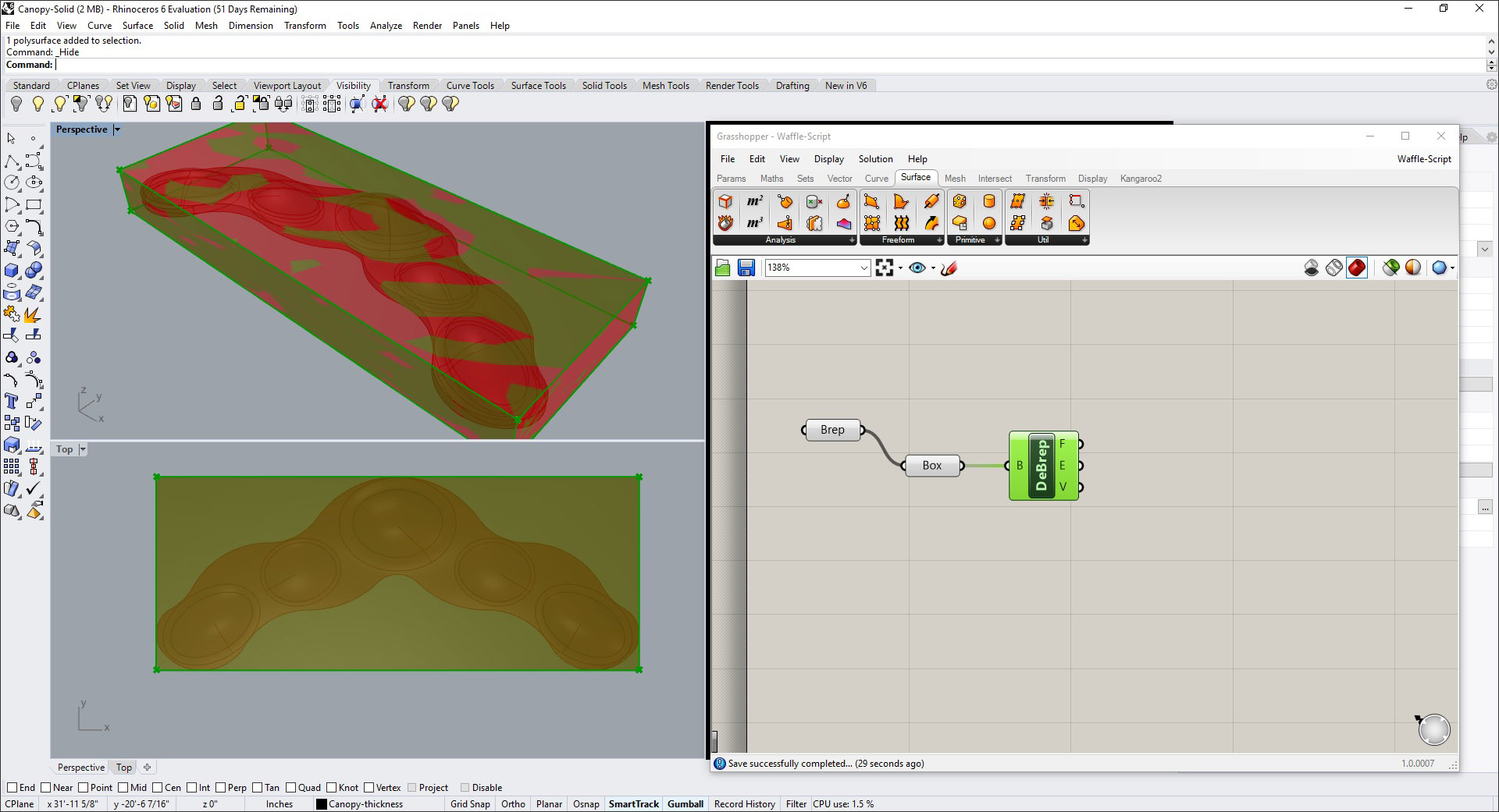
Continuing with the script, add the components Box and Deconstruct Brep (DeBrep) as shown, with the input going from the Brep to the Box and from the Box to the DeBrep. The Box component helps to define the direction of the ribs, while the DeBrep component breaks down the box surface to its constituents faces, edges, and vertices.
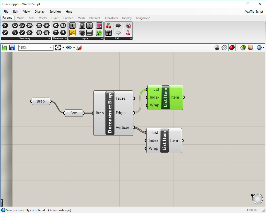
As the next step, we will add two list items to capture the list of the edges and vertices of the DeBrep. There is no visible change to the model since no graphical command has been added to the script.
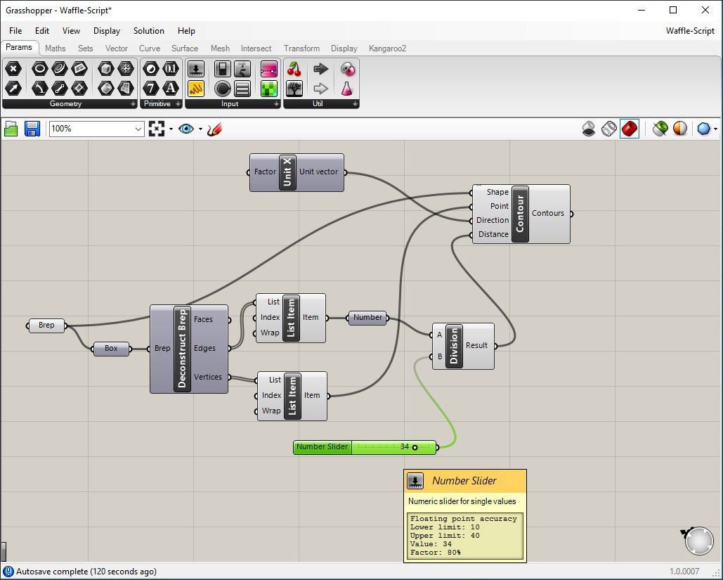
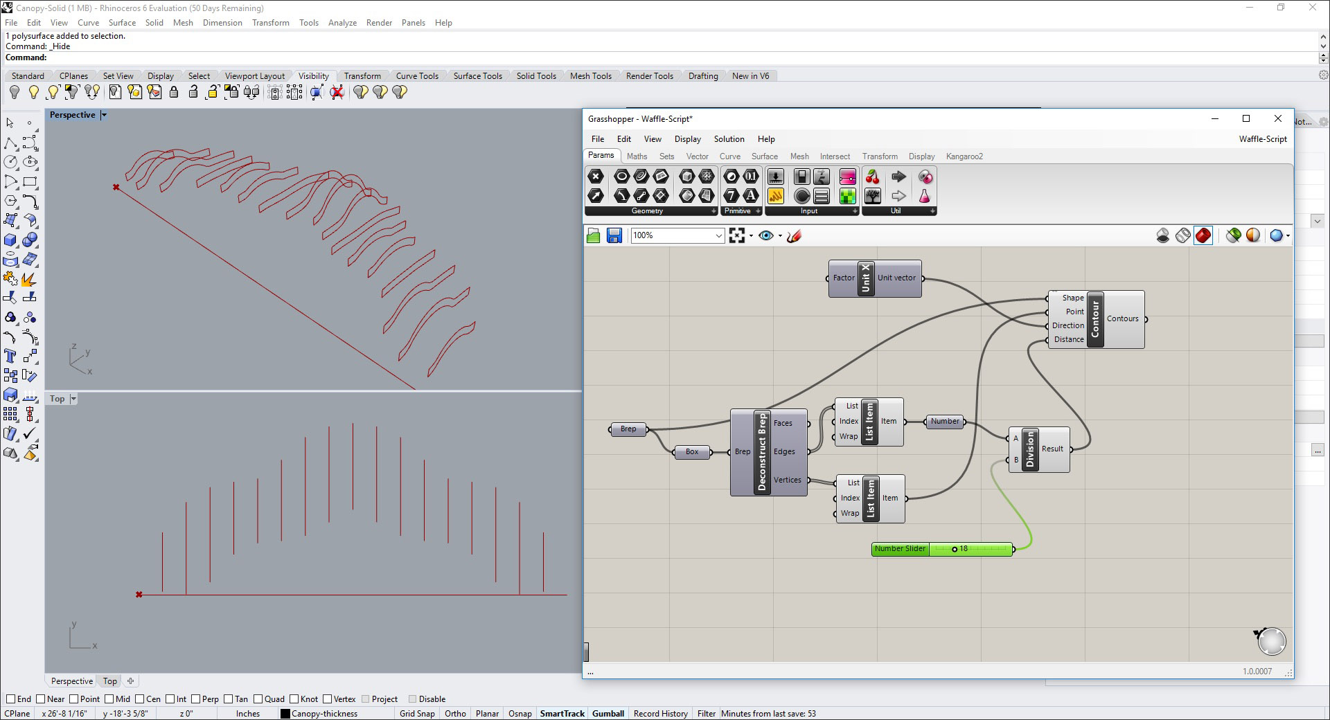
We now need to create the contours in each direction for the ribs of the waffle slab. The script for this involves multiple components. We will start by placing the Contour component, which needs four inputs: the original Brep for the shape; the List Item for the vertices as the points; an additional Unit X component to indicate the perpendicular direction (we are starting with the contours along the Y direction first); and the distance, which is derived by dividing the length of the DeBrep (captured by a Number component connected to the List Item for the edges) by the desired spacing, using a Division component and a Number Slider.
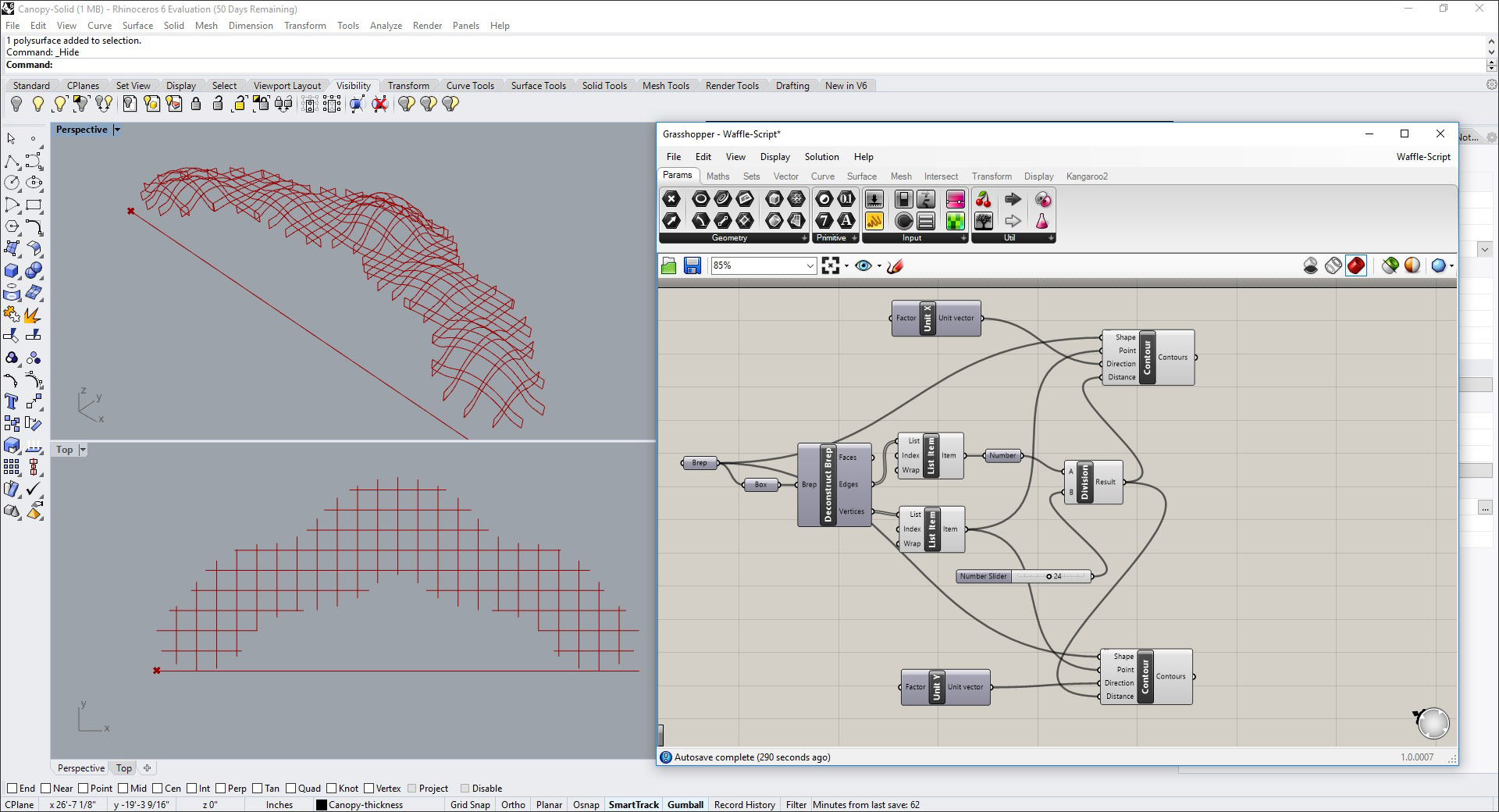
If you now see the canopy object in Rhino to which this script is being applied, you can see the contours and how their spacing can be changed by simply adjusting the value in the Number Slider, whose minimum and maximum limits you can set as required. The Rhino display in Figure 14 was generated by turning off the visibility of the Rhino object as well as deactivating the preview of all the Grasshopper components except the contours.
We can now create another Contour component to create the ribs along the X direction. This requires creating a new Unit Y component. The other inputs are the same, assuming you want the same spacing for the ribs in both directions. If not, you would need to create another Division and Number Slider for the new contours.
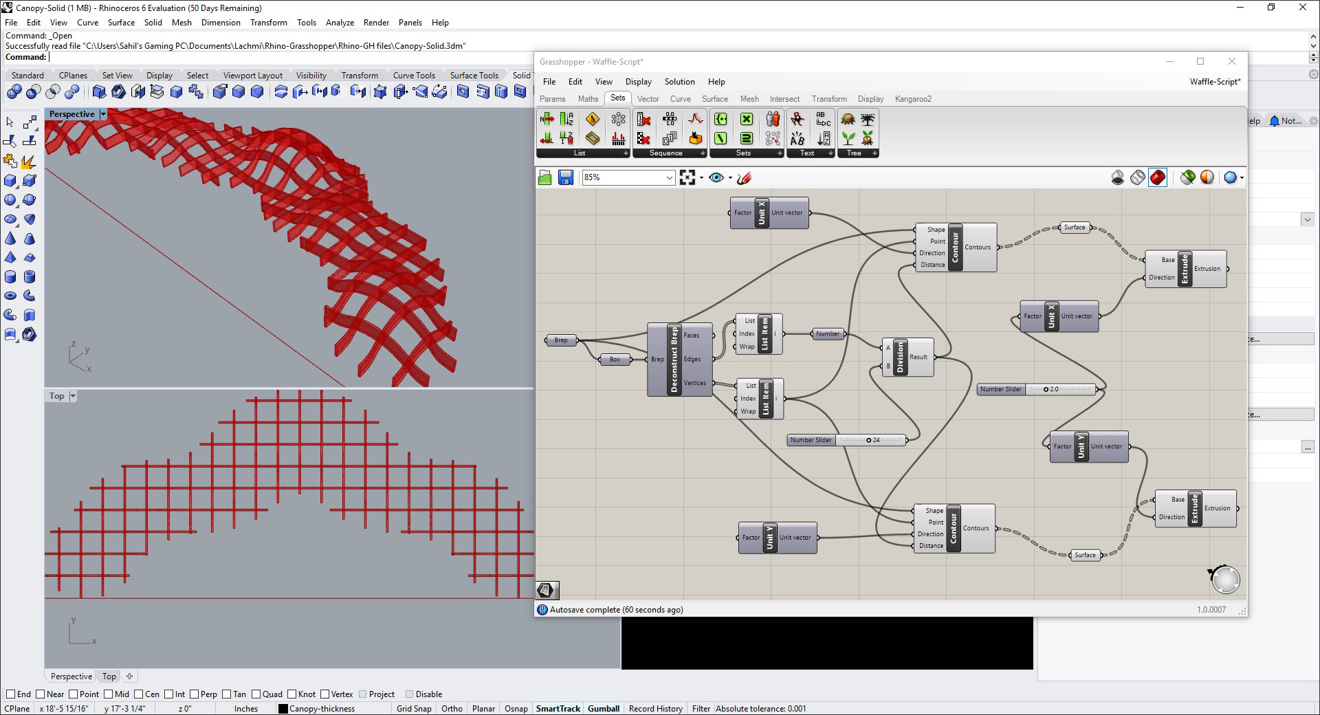
Next, we want to give the contour surfaces a thickness. Since they are generated as curves, we will first convert them to surfaces using the Surface component. We can then use the Extrude component that uses the contour surfaces as input, and the distance of the extrusion in a specific direction, which in the case of this script, is provided by additional Unit X and Unit Y components for the two directions and a Number Slider for defining the width of the ribs. Again, the width can be adjusted by simply manipulating the value in the slider.
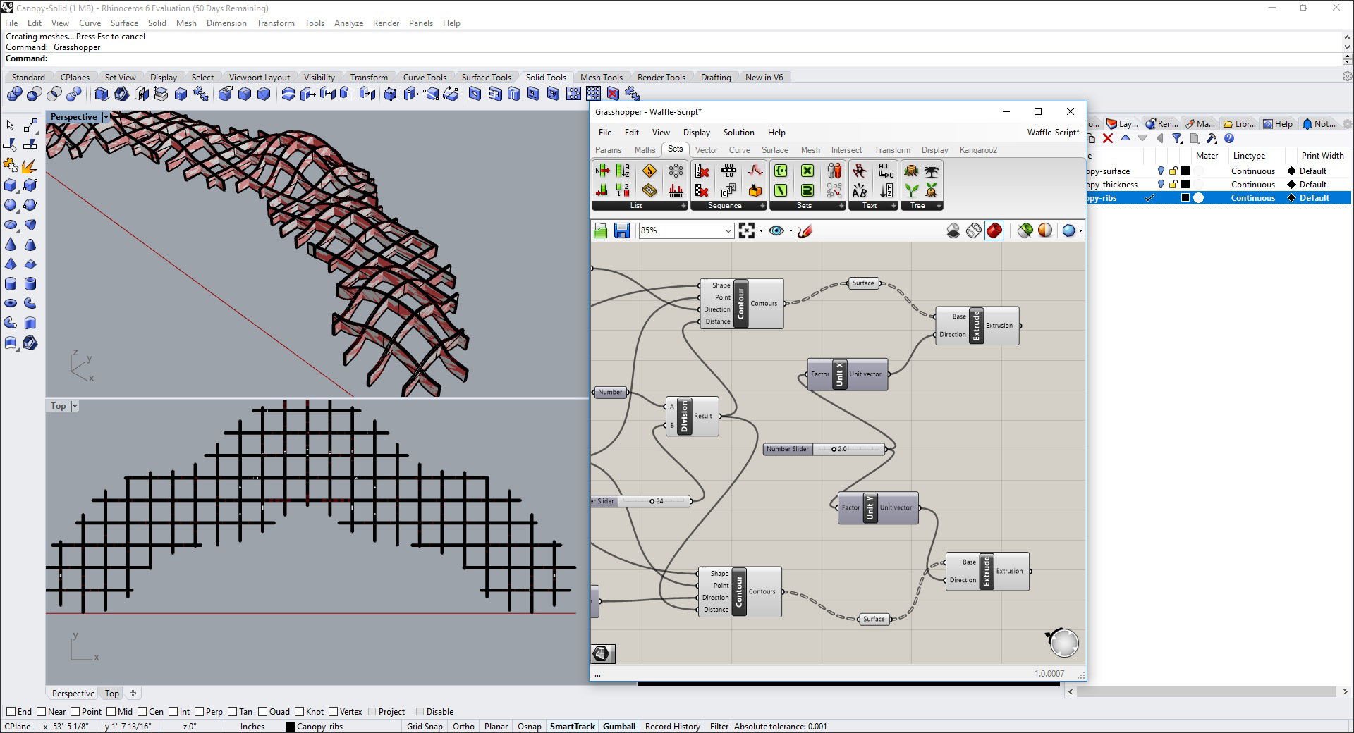
Once the spacing of the ribs and their thickness has been set as required using the Number Slider, we can transform the Grasshopper objects to actual Rhino objects by “baking” them. This involves selecting the two Extrude components and selecting Bake from the right-click menu. Among the different options in the dialog that comes up, you can choose the layer these ribs will be placed on. Figure 17 shows them placed on a separate layer in the Rhino model.
You can now turn off the Grasshopper window and complete the edge rib of the canopy in Rhino to have the waffle structure model.
We can see that creating a Grasshopper script for a waffle structure takes more time than modeling it directly in Rhino, but it is well worth it—once the script is written, the design is automated and changes can be made instantaneously, allowing many different design options to be explored before finalizing on one. Also, once the script is created, it can be used on multiple projects. Similar to object libraries and CAD and BIM standards, an office can have an entire library of these scripts, ready to be applied to different Rhino models to explore different design forms for its projects.
If a physical prototype of a waffle structure needs to be created, some additional steps are required—creating the notches in the ribs at the intersections and then unfolding them to the XY work plane for laser cutting by a CNC machine. The Grasshopper script that has been created so far can be further extended to automate this process as well. There is also a separate Grasshopper component called Bowerbird that can be used.
The Grasshopper script created for the waffle structure in this tutorial can be downloaded here.
An excellent introduction to Grasshopper is provided at:
https://vimeopro.com/rhino/grasshopper-getting-started-by-david-rutten/video/79843282

Mark Loomis is a Principal at MP Studio, a full-service landscape architecture studio located in San Antonio, Texas. He has 17 years of experience in the landscape architecture industry and 14 years of practice in the related fields of architectural stonework and precast concrete technical detailing. He has a keen interest in 3D modeling, parametric modeling and generative design.
Have comments or feedback on this article? Visit its AECbytes blog posting to share them with other readers or see what others have to say.
AECbytes content should not be reproduced on any other website, blog, print publication, or newsletter without permission.